102 Troubleshooting and problem solving
DDIC LED
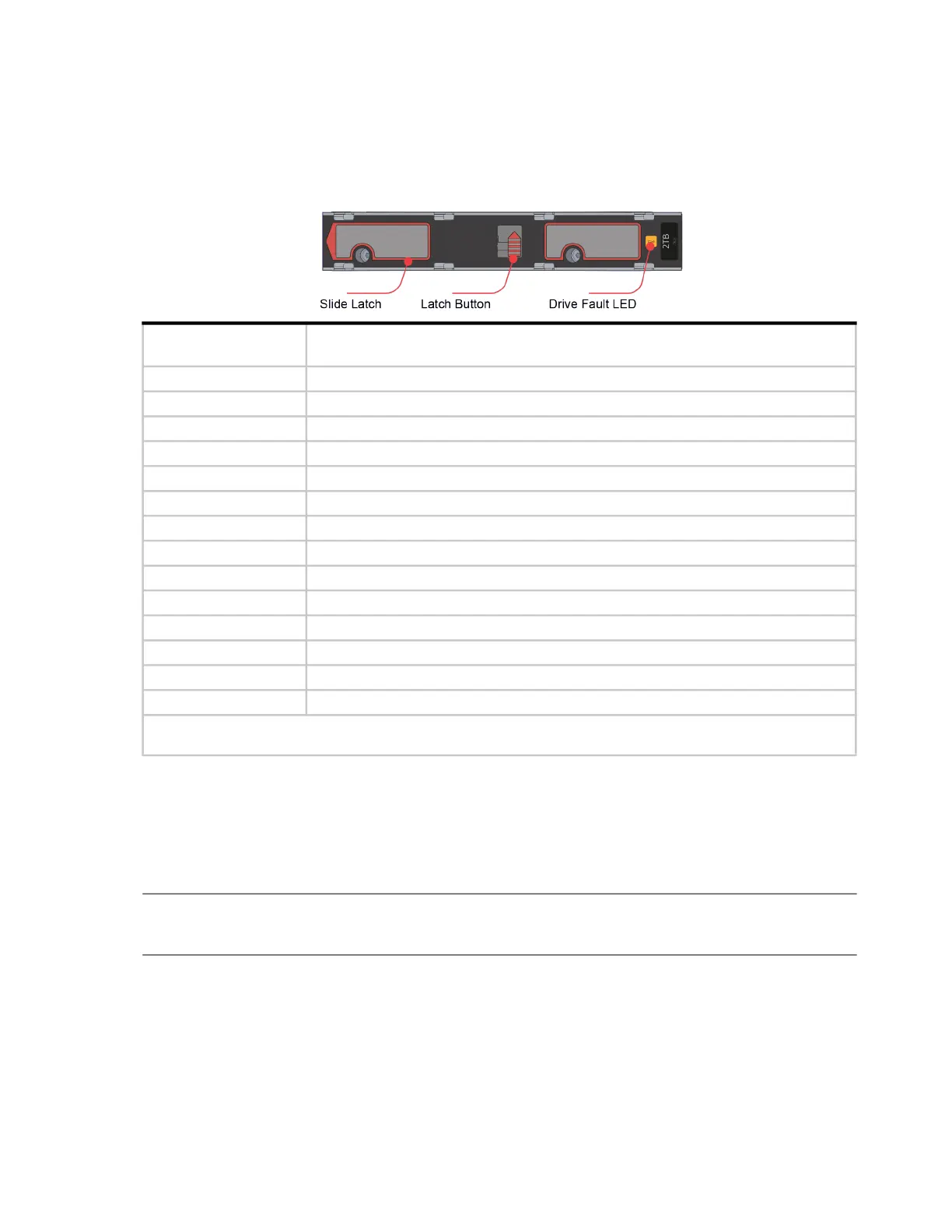
The DDIC supports LFF 3.5" and SFF 2.5" disks as shown in Figure 48 (page 56) and Figure 49 (page 56). The
illustration below shows the top panel of the DDIC as viewed when the disk is aligned for insertion into the drawer
slot. See also Figure 25 (page 33) and Figure 26 (page 33).
Figure 76 LEDs: DDIC – 5U enclosure disk slot in drawer
Each DDIC has a single Drive Fault LED. A disk drive fault is indicated if the Drive Fault LED is lit amber. In the
event of a disk failure, follow the procedure in “Replacing a DDIC” (page 134).
IOM LEDs
NOTE: The expansion module CRU is common to 2U and 5U enclosures. For information about expansion
module LEDs see “12Gb/s expansion module LEDs” (page 52).
Temperature sensors
Temperature sensors throughout the enclosure and its components monitor the thermal health of the storage system.
Exceeding the limits of critical values will cause a notification to occur.
Drive Fault LED
(Amber)
Status/condition*
Off Off (disk module/enclosure)
Off Not present
Blink: 1s on/1s off Identify
Any links down: On Drive link (PHY lane) down
On Fault (leftover/failed/locked-out)
Off Available
Off Storage system: Initializing
Off Storage system: Fault-tolerant
Off Storage system: Degraded (not critical)
Blinking: 3s on/1s off Storage system: Degraded (critical)
Off Storage system: Quarantined
Blinking: 3s on/1s off Storage system: Offline (dequarantined)
Off Storage system: Reconstruction
Off Processing I/O (whether from host or internal activity)
*If multiple conditions occur simultaneously, the LED state will behave as indicated by the condition listed earliest in the
table, as rows are read from top to bottom.
DDIC
(longitudinal view–top face of carrier)
 Loading...