60 Installation
3-The Storage Management Console is introduced in “Accessing the SMC” (page 94). See the Storage Manager Guide or online help for
additional information.
Planning for installation
Before beginning the enclosure installation, familiarize yourself with the system configuration requirements. The
figures listed below show the locations for each plug-in module:
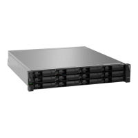
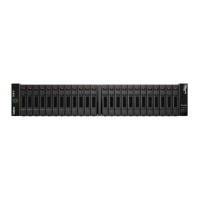
• 2U12 front panel: see Figure 10 (page 26)
• 2U24 front panel: see Figure 11 (page 26)
• 2U controller enclosure rear panel: see Figure 12 (page 27)
• 2U expansion enclosure rear panel: see Figure 16 (page 27) (product option)
• 5U front panel: see Figure 25 (page 33) (eBezel) and Figure 26 (page 33) (drawer with slot index)
• 5U expansion enclosure rear panel: see Figure 27 (page 34) (product option)
IMPORTANT: Installation work should be performed by qualified service personnel.
NOTE: Whether 2U or 5U, DS EXP enclosures use a common expansion module. See Figure 21 (page 29).
Preparing for installation
NOTE: Enclosure configurations
• 2U enclosures are delivered with CRUs and all drive carrier modules installed.
• 5U enclosures are delivered with many CRUs installed; however, DDICs must be installed during system setup.
CAUTION: Lifting enclosures
• A 2U enclosure—together will all its component parts—is too heavy for one person to lift and install into the
rack cabinet. Two people are required to safely move a 2U enclosure.
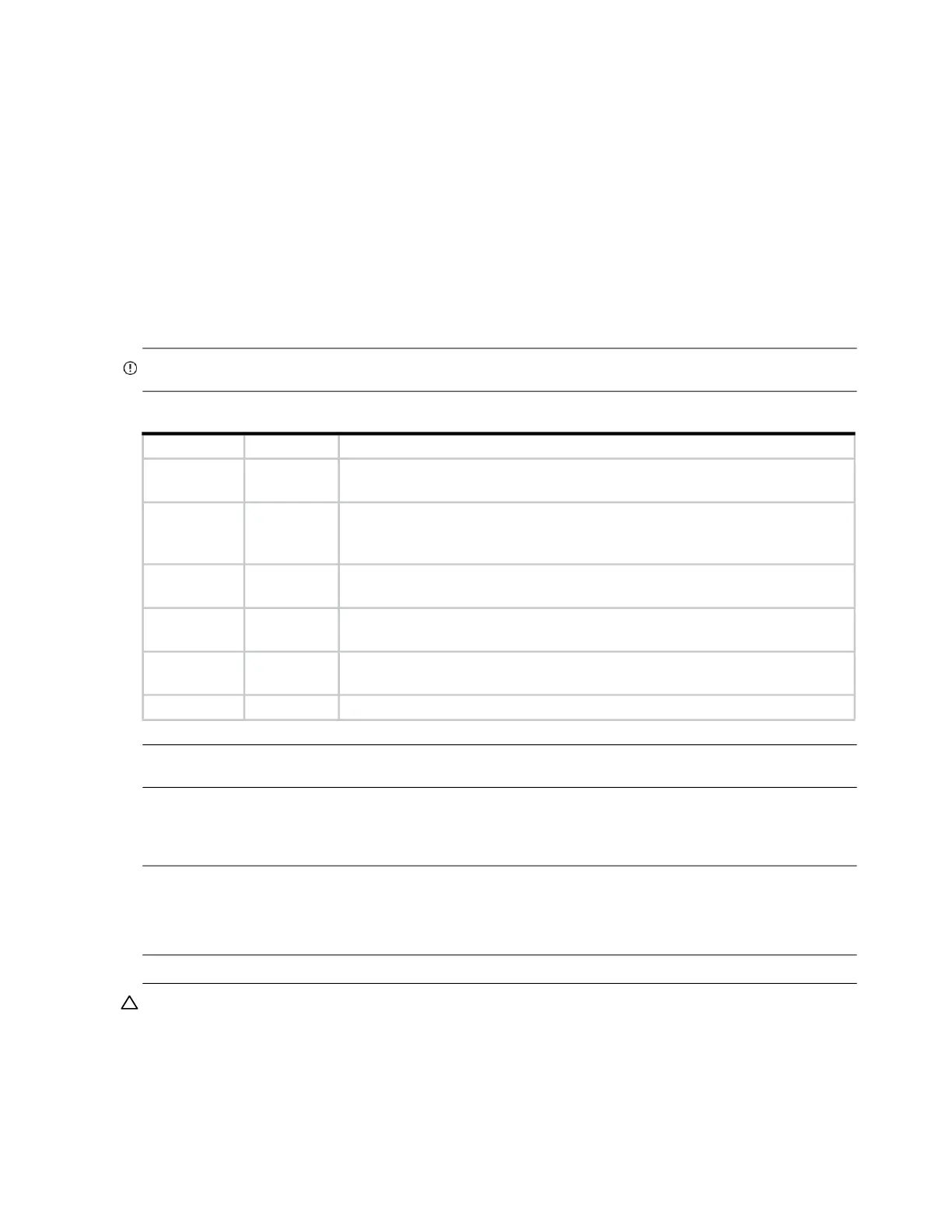
Table 10 Storage system configuration
Module type Location Description
Drive carrier
modules
2U Front
panel
All drive slots must hold either a drive carrier or dummy drive carrier module.
Empty slots are not allowed. At least one disk must be installed.
DDIC 5U Front
panel
drawers
Maximum 84 disks are installed (42 disks per drawer)
Minimum 14 disks are required. Follow drawer population rules on page 57.
Power cooling
modules
2U Rear
panel
Two PCMs provide full power redundancy, allowing the system to continue to
operate while a faulty PCM is replaced.
Power supply
unit modules
5U Rear
panel
Two PSUs provide full power redundancy, allowing the system to continue to
operate while a faulty PSU is replaced.
Fan cooling
modules
5U rear panel Five FCMs provide airflow circulation, maintaining all system components
below the maximum temperature allowed.
I/O modules Rear panel Two IOMs must be installed for this configuration (RBOD and EBOD).
 Loading...