70 Installation
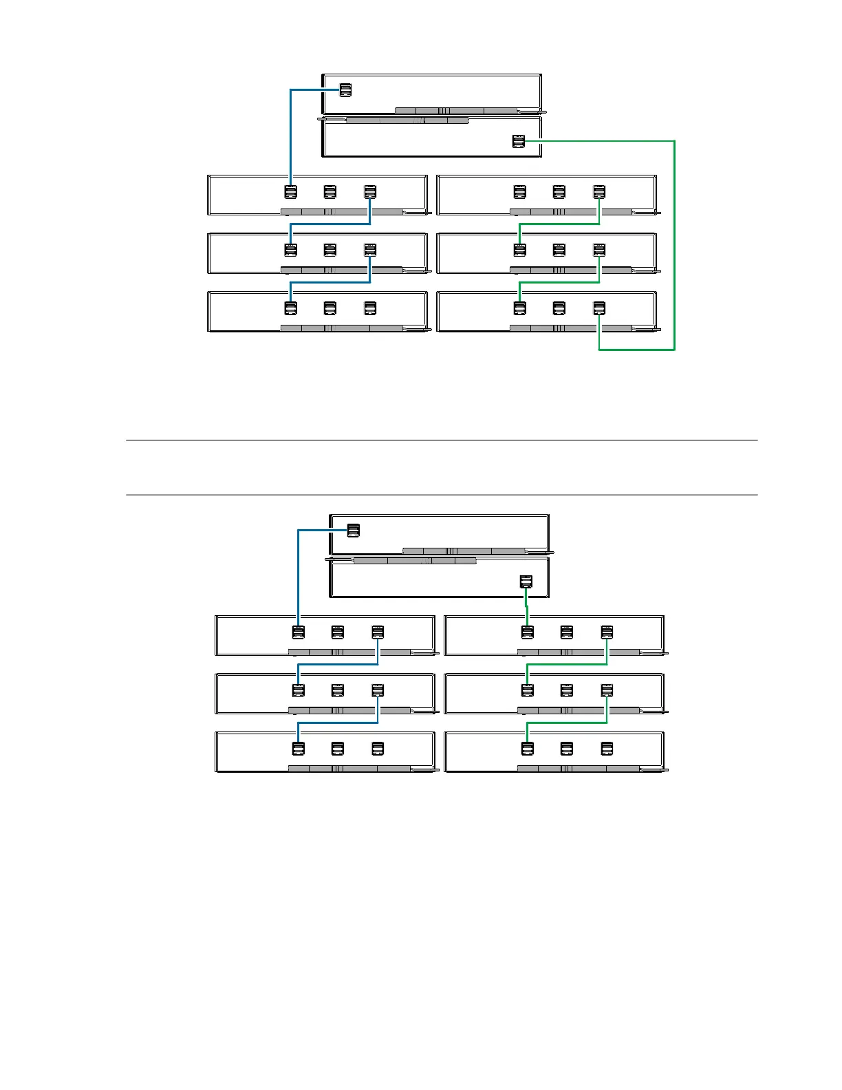
Figure 56 Cabling connections between a 2U controller enclosure and D3284 expansion enclosure–reverse
Figure 56 and Figure 57 show maximum configuration cabling for a DS6200/DS4200 controller enclosure with
D3284 expansion enclosures.
NOTE: See also Figure 21 (page 29) and the IMPORTANT entry beneath that figure. Refer to these diagrams
when cabling D3284 expansion enclosures together with DS6200/DS4200 controller enclosures.
Figure 57 Cabling connections between a 2U controller enclosure and D3284 expansion
enclosure–straight-through
The comparative characteristics of using either reverse cabling or straight-through cabling methods are discussed
beneath Figure 55 (page 68).
Reverse cabling
Controller A
Controller B
0A
0B
1A 1B
2A 2B
3A 3B
A C
A C
A C
A C
A C
A C
Straight-through cabling
Controller A
Controller B
0A
0B
1A 1B
2A 2B
3A 3B
A C
A C
A C
A C
A C
A C
 Loading...