Electrical installation − EMS version
Devices in a power range of 0.75 ... 4 kW (3/PE AC 400 V)
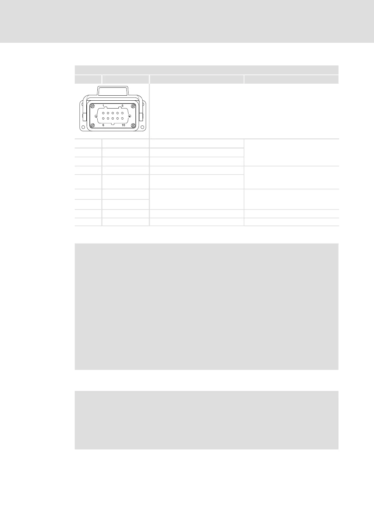
Terminal assignment of the power connections
7
125
EDS84DPS424 EN 5.0
X21 − motor connection − device version E84DxH...
Pin Connection Description Data
Type Han 10E, sockets
84DWTX0212
1 U Motor phase U
Max. 4 mm
2
Max. output voltage: mains voltage
Max. permanent output current:
type−dependent
2 V Motor phase W
3 W Motor phase V
4 BD1 Motor holding brake
Max. 4 mm
2
9 BD2 Motor holding brake (reference
conductor)
5 +PTC
Motor temperature monitoring Max. 4 mm
2
PTC thermistor (PTC) or thermal
contact (NC contact)
10 −PTC
6, 7, 8 n. c. − −
PE PE conductor Max. 4 mm
2
, above housing
Stop!
Damage of the devices
A defective motor holding brake or a short circuit on the X21 connection
(motor and built−on accessories) causes internal damage to the device.
Possible consequences:
ƒ If a defective motor holding brake is connected, the replacement device is
also damaged immediately.
Protective measures:
ƒ When devices are replaced due to malfunction of the brake control, ensure
that defect−free motor holding brakes are connected.
ƒ Check whether the motor holding brake and the connecting cable are free
from defects.
ƒ Replace or repair defective components.
Note!
In the Lenze setting, the temperature monitoring of the motor is activated! To
start motors without thermal detectors, the response of the motor
temperature monitoring must be deactivated (C00585). Alternatively, a wire
jumper between +PTC and −PTC can be used to simulate a normal
temperature.