Electrical installation − EMS version
Devices in a power range of 0.75 ... 4 kW (3/PE AC 400 V)
Terminal assignment of the power connections
7
124
EDS84DPS424 EN 5.0
Motor connection
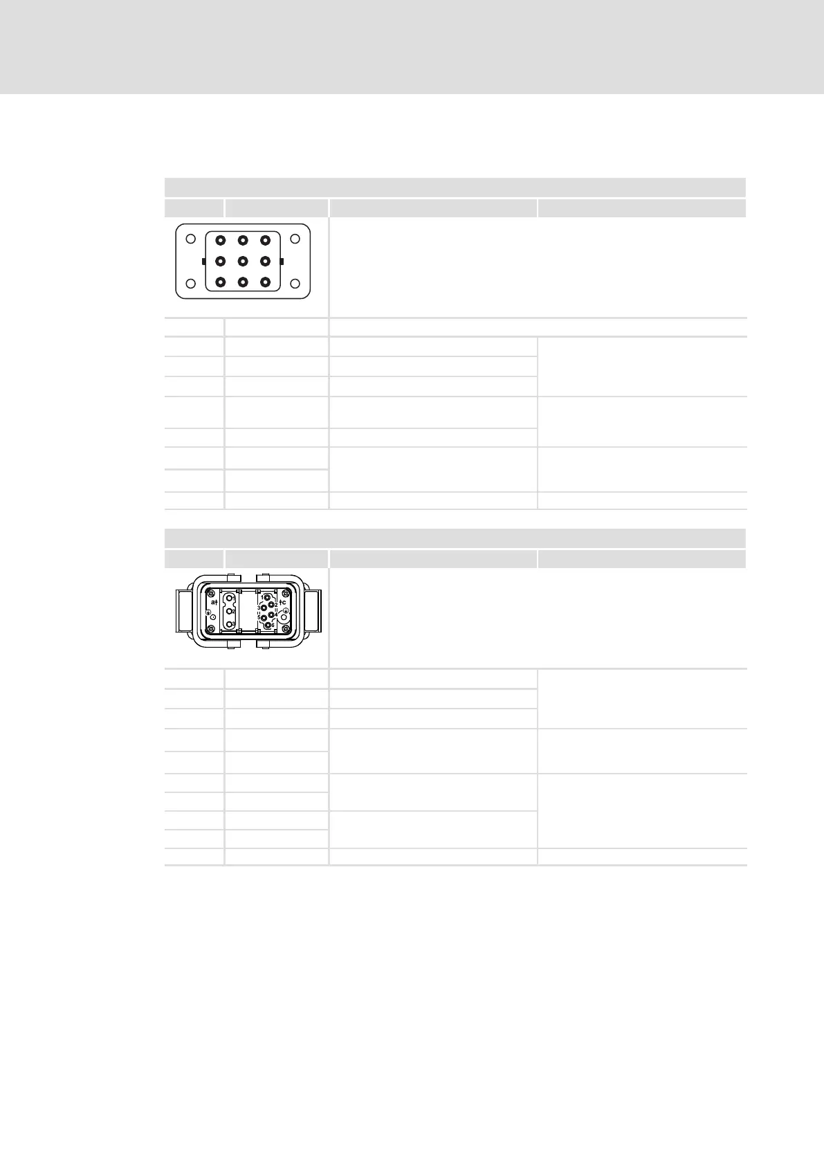
X21 − motor connection − device version E84DxxC...
Pin Connection Description Data
12
3
4
5
67
8
+
Type Q8/0, sockets
Use Lenze system cable:
EYP0037xxxxxxxxQ10, 8−core, 1.5 mm
2
EYP0038xxxxxxxxQ11, 8 core, 2.5 mm
2
84DWTX0210
2 n. c. Grooved pin as a protection against mix−up with power bus
1 U Motor phase U
Max. 4 mm
2
Max. output voltage: mains voltage
Max. permanent output current:
type−dependent
3 W Motor phase W
7 V Motor phase V
4 BD2 Motor holding brake (reference
conductor)
Max. 4 mm
2
6 BD1 Motor holding brake
5 +PTC
Motor temperature monitoring Max. 4 mm
2
PTC thermistor (PTC) or thermal
contact (NC contact)
8 −PTC
PE PE conductor Max. 4 mm
2
X21 − motor connection − device version E84DxxB...
Pin Connection Description Data
Type Modular, sockets
Use Lenze system cable:
EYP0039xxxxxxxxQ08, 10−core, 1.5 mm
2
EYP0040xxxxxxxxQ09, 10−core, 2.5 mm
2
84DWTX0211
a1 U Motor phase U
Max. 6 mm
2
Max. output voltage: mains voltage
Max. permanent output current:
type−dependent
a2 V Motor phase V
a3 W Motor phase W
c1 +PTC
Motor temperature monitoring Max. 4 mm
2
PTC thermistor (PTC) or thermal
contact (NC contact)
c6 −PTC
c2 ~
Supply voltage of brake rectifier Max. 4 mm
2
V
rated
= mains voltage−dependent
The brake rectifier is mounted in the
terminal box of the motor.
c3 ~
c4 S1
Switch for separation on the DC side
c5 S2
PE PE conductor Max. 6 mm
2