5 Motor control & motor settings
5.10 Synchronous motor (SM): Pole position identification
103
Lenze · i700 servo inverter · reference manual · DMS 3.0 EN · 06/2016 · TD06
_ _ _ _ _ _ _ _ _ _ _ _ _ _ _ _ _ _ _ _ _ _ _ _ _ _ _ _ _ _ _ _ _ _ _ _ _ _ _ _ _ _ _ _ _ _ _ _ _ _ _ _ _ _ _ _ _ _ _ _ _ _ _ _
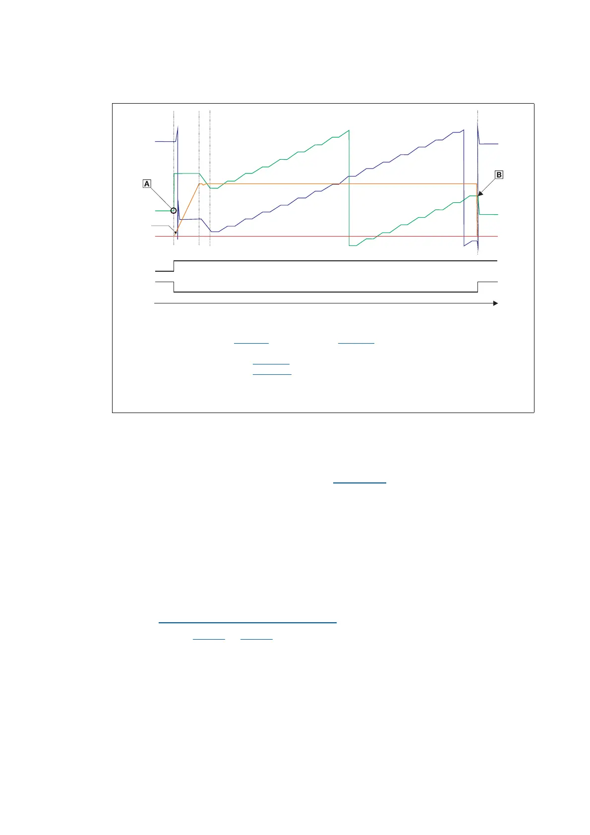
[5-2] Chronological sequence of the pole position identification (360°)
Preconditions for the execution
• The motor must not be braked or blocked during the pole position identification.
• The servo inverter is free of errors and is in the "Switched on
" device status.
Response of the motor during the execution
During the pole position identification the rotor aligns itself. The motor shaft moves by max. one
electrical revolution which causes the corresponding movement of the connected mechanical
components!
How to execute the pole position identification PPI (360°):
1. If the servo inverter is enabled, inhibit the servo inverter.
Enable/inhibit operation via control word
( 52)
2. Set object 0x2825
(or 0x3025 for axis B) to "5" to change to the "Pole position identification
PPI (360°)" operating mode.
3. Before the PLI can be started, the works mentioned in the following have to be completed.
All setting values are examples and apply to the motor 115UDD305BBWBA-SKTY
Start of the pole position identification
End of the pole position identification (IMP = High)
Current position of the rotor ( 0x6064:0
, actual position or 0x2DDE:0, actual position of rotor angle)
Commutation angle of current vector, variable of the motor control (cannot be displayed in case of i700)
Amplitude of the d current vector ( 0x2DD1:1
actual d current)
Amplitude of the q current vector ( 0x2DD1:2
actual q current), is not used for PPI_360°
Structure of the d current vector at electrical 45° (starting angle)
Angular change of the d current vector to electrical 0°; alignment of the rotor
15 angular changes by 22.5° each and subsequent plausibility check