5 Motor control & motor settings
5.9 Setting the feedback system for the servo control
99
Lenze · i700 servo inverter · reference manual · DMS 3.0 EN · 06/2016 · TD06
_ _ _ _ _ _ _ _ _ _ _ _ _ _ _ _ _ _ _ _ _ _ _ _ _ _ _ _ _ _ _ _ _ _ _ _ _ _ _ _ _ _ _ _ _ _ _ _ _ _ _ _ _ _ _ _ _ _ _ _ _ _ _ _
function of the CiA device status and the setting in subindex 4 (Hiperface communication error:
Response):
5.9.6 Detection of changed settings of the feedback system
Bit 0 of the Lenze status word 2 (0x2833 or 0x3033 for axis B) displays whether the settings of the
feedback system have been changed since the Not ready to switch on
has been left. In case of a
change, bit 0 is set to "1".
A transition to the Operation enabled
state causes bit 0 to be reset again to "0". In all device states,
the monitoring of changes at the following objects remains active:
After a controller enable, bit 0 of the Lenze status word 2 is always reset to "0".
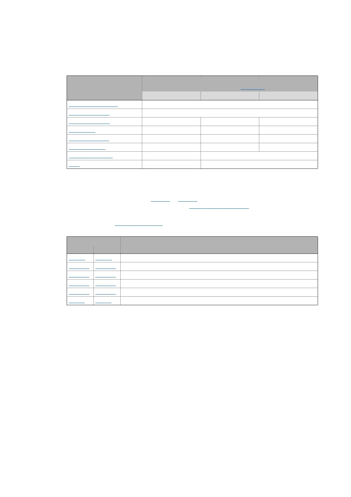
CiA device state Response in the event of an error
(depending on the error responses set in the Subindex 4
)
0: No Response 1: Trouble 2: Warning
Not ready to switch on
Warning
Switch on disabled
Warning
Ready to switch on
- Fault Warning
Switched on
- Fault Warning
Operation enabled
- Fault Warning
Quick stop active
- Fault Warning
Fault reaction active
- Warning
Fault
- Warning
Object Name
Axis A Axis B
0x2C40 0x3440 Encoder: Type
0x2C41:2
0x3441:2 Hiperface: User defined - Type code
0x2C41:3
0x3441:3 Hiperface: User defined - Number of revolutions
0x2C41:5
0x3441:5 Hiperface: Serial number
0x2C42:1
0x3442:1 Encoder: Increments / revolution
0x608F 0x688F Position encoder resolution