Lenze · i700 servo inverter · reference manual · DMS 3.0 EN · 06/2016 · TD06 182
7 CiA402 device profile
7.4 Device control
_ _ _ _ _ _ _ _ _ _ _ _ _ _ _ _ _ _ _ _ _ _ _ _ _ _ _ _ _ _ _ _ _ _ _ _ _ _ _ _ _ _ _ _ _ _ _ _ _ _ _ _ _ _ _ _ _ _ _ _ _ _ _ _
7.4.1 Commands for the device status control
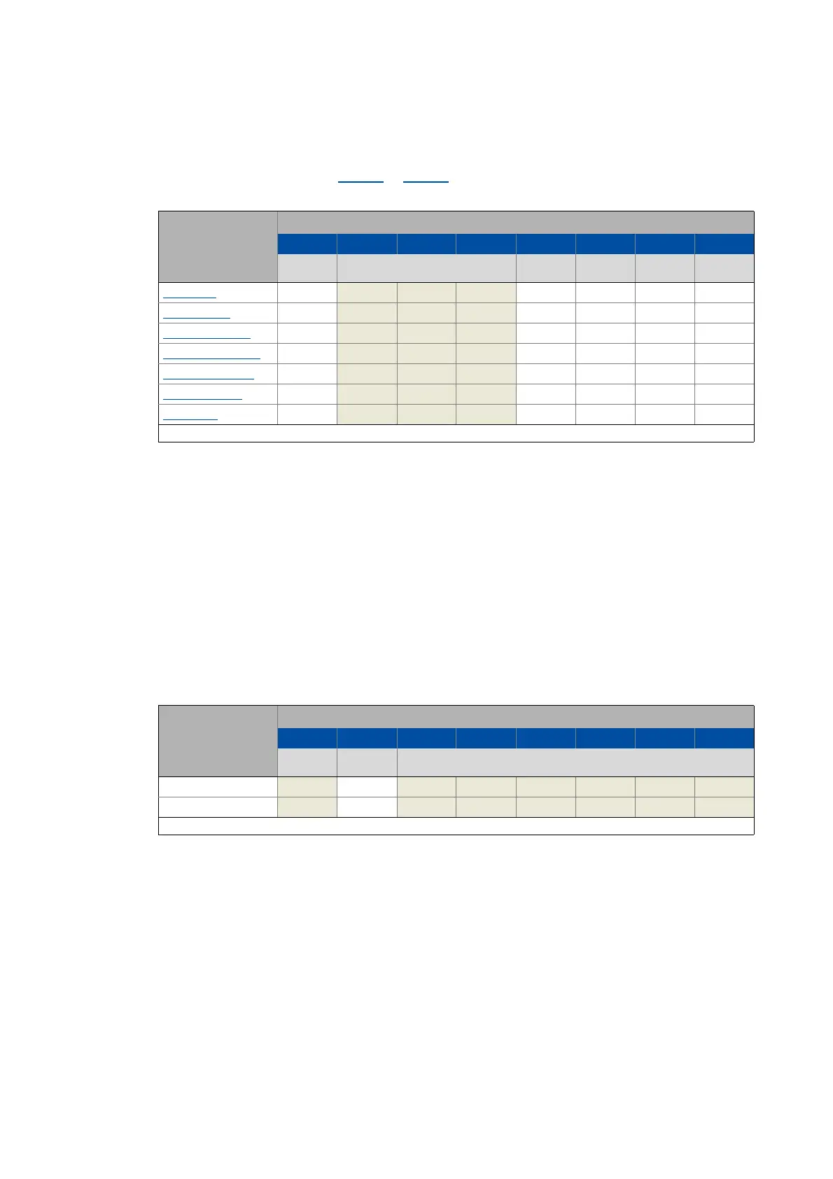
Via the CiA402 control word (0x6040 or 0x6840 for axis B), commands can be triggered that serve
to navigate the servo inverter to a specific device state:
Tip!
The greyed out control bits listed in the table are not important for the activation of
commands but only serve to improve readability of the bit patterns.
A PLC program of a PLCopen control can, for instance, trigger several commands for state
changes in a row by the level change at the bRegulatorOn input of the "MC_Power" block.
In the mentioned example, these device commands are "switch-off" and "switch-on" in this
order.
Detailed information on the different commands can be obtained from the following
subchapters.
Further Lenze-specific control bits (bits 8 ... 15)
Command Bit pattern in the Controlword
Bit 7 Bit 6 Bit 5 Bit 4 Bit 3 Bit 2 Bit 1 Bit 0
Fault reset Control bits depending on the operating
mode
Enable
operation
Activate
quick stop
Enable
voltage
Switching on
Shutdown 0 X X XX110
Switching on
0 X X XX111
Enable operation
0 X X X1111
Activate quick stop 0 X X XX01X
Disable operation
0 X X X0111
Disable voltage
0 X X XXX0X
Fault reset 0 1 X X XXXXX
X = Status not significant
Device control
command
Bit pattern in the Controlword
Bit 15 Bit 14 Bit 13 Bit 12 Bit 11 Bit 10 Bit 9 Bit 8
Reserved Release
brake
Reserved
Apply brake X0X X X X X X
Release brake X1X X X X X X
X = Status not significant