Functions
Leuze electronic RSL 430 39
PF1.1
PF1.2
PFA…
PFA.x
1
2 3
5
4
0
1
A1.2
0
0
0
1
XX XX
0
1
0
0
A1.2 & A1.x A1.x
0
1
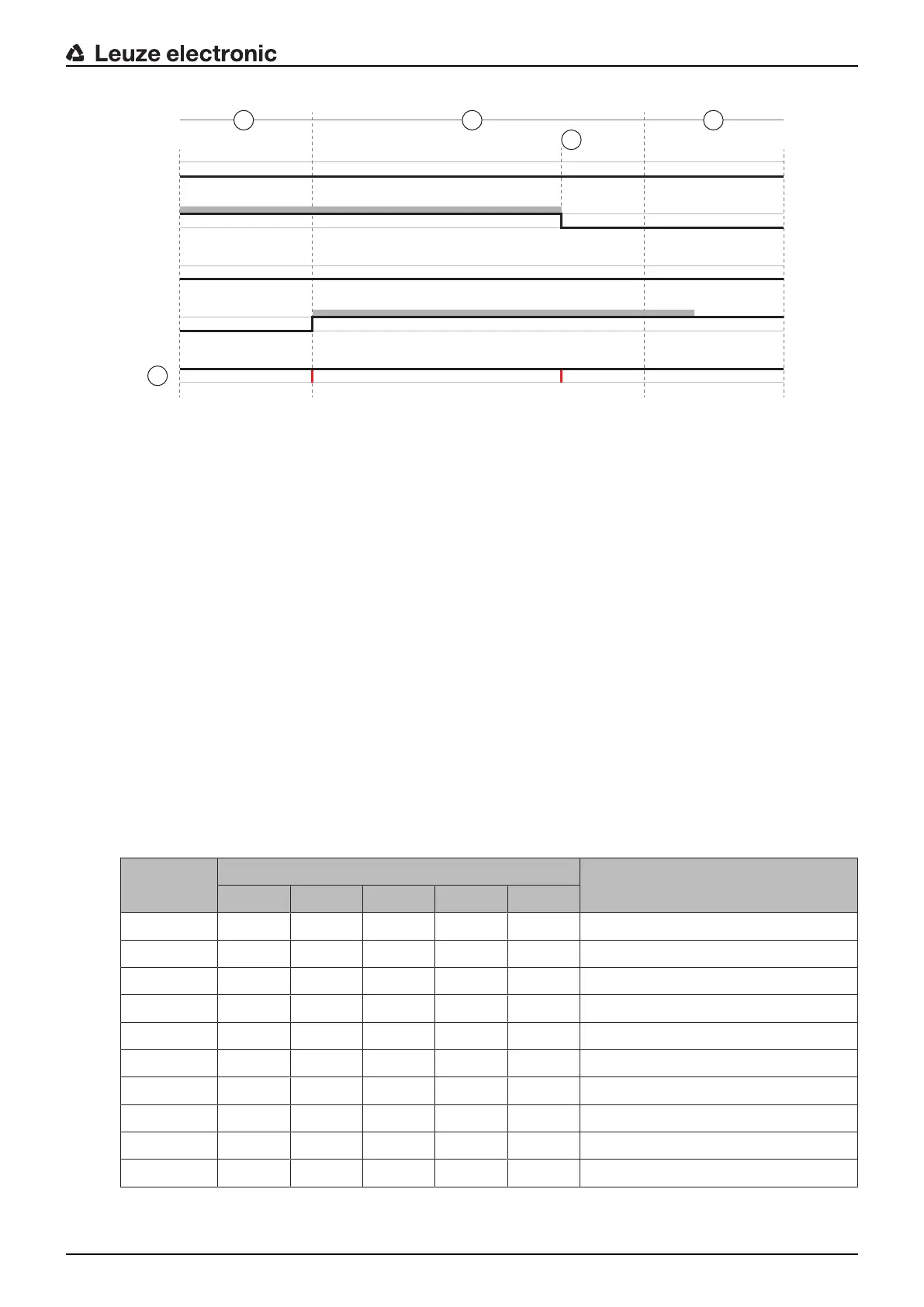
1 Active protective field
2 An old protective field is active
3 Set changeover time
4 A new protective field is active
5 Changeover complete
PF Field pair or quad
XX Field pair changeover
Fig.5.2: Signal/time diagram: Overlapped monitoring
5.7.3
Changeover of ten field pairs in changeover mode Fixed changeover moment
Changeover mode Fixed changeover moment: The field pair changeover must take place within the con-
figurable changeover time, i.e. after the changeover time has expired, a valid and stable input connection
must be present. The old field pair is monitored during the changeover time.
• The previously active field pair is monitored during the changeover time.
• The changeover time starts when the safety sensor registers a change at control inputs F1 to F5. When
the changeover time has expired, only one field pair should still be active.
• Monitoring of the newly activated field pair starts when the changeover time has expired.
• The changeover time is specified with the configuration and diagnostics software (see chapter 9.4.4
"Creating and configuring protective/warning field pairs").
Tab.5.6: Connection of control inputs F1 to F5 with activation of field pairs A1.1 to A1.10 for protective function A
Field pair Control input Description
F1 F2 F3 F4 F5
A1.1 1 0 0 0 0 Field pair A1.1 is active
A1.2 0 1 0 0 0 Field pair A1.2 is active
A1.3 0 0 1 0 0 Field pair A1.3 is active
A1.4 0 0 0 1 0 Field pair A1.4 is active
A1.5 0 0 0 0 1 Field pair A1.5 is active
A1.6 1 1 1 1 0 Field pair A1.6 is active
A1.7 1 1 1 0 1 Field pair A1.7 is active
A1.8 1 1 0 1 1 Field pair A1.8 is active
A1.9 1 0 1 1 1 Field pair A1.9 is active
A1.10 0 1 1 1 1 Field pair A1.10 is active
In the case of two protective functions, connection of control inputs F6 to F10 applies analogously for acti-
vation of field pairs B1.1 to B1.10 for protective function B.