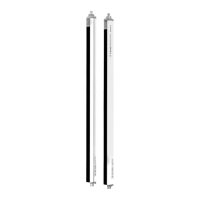
Electrical connection
Leuze electronic RSL 430 71
8.2.2
Connection cable with M30 connector
The safety sensor is equipped with a 30-pin M30 connector.
10
6
3
7
11
16
12
18
17
23
22
27
26
30
21
29
25
28
24
20
15
19
13
14
8
9
4
5
1
2
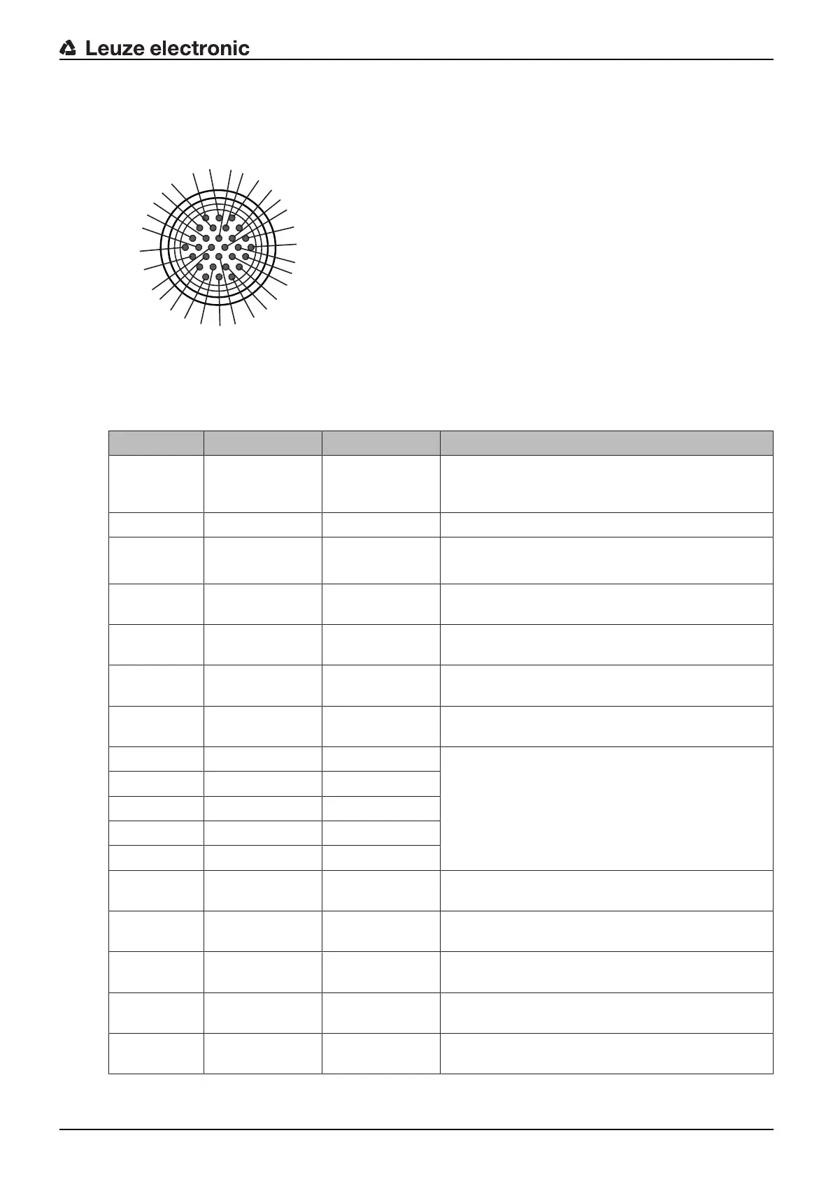
Fig.8.1: Pin assignment for M30 connector, 30-pin
Tab.8.3: Pin assignment
Pin Core color Signal Description
1 White RES1 Start/restart input
protective functionA
acknowledgment
2 Brown 24V Supply voltage
3 Green EA1 Contactor monitoring OSSDA
Alternatively: State signaling, configurable
4 Gray OSSDA1 Safety-related switching output
protective functionA
5 Pink OSSDA2 Safety-related switching output
protective functionA
6 Red MELD Output signal
state signaling, configurable
7 Yellow A1 Output signal
state signaling, configurable
8 Black F1 5 function inputs for field pair changeover
protective functionA
Field pair changeover with 100 field pairs (A1.x) –
2nd position
Field pair changeover with multi configuration (A1.x)
within one bank
9 Violet F2
10 Gray/pink F3
11 Blue/red F4
12 White/Green F5
13 Brown/Green SE1 Linkage input
(E-Stop, OSSD – external device)
14 White/Yellow SE2 Linkage input
(E-Stop, OSSD – external device)
15 Yellow/Brown A2 Output signal
state signaling, configurable
16 White/Gray A3 Output signal
state signaling, configurable
17 Gray/Brown A4 Output signal
state signaling, configurable