Connector locations 5-5
5025-2xx, 4xx
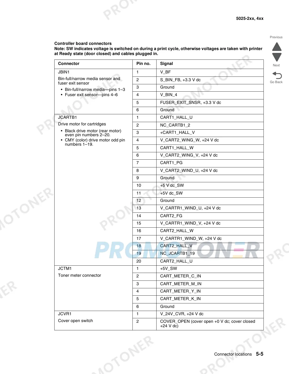
Controller board connectors
Note: SW indicates voltage is switched on during a print cycle, otherwise voltages are taken with printer
at Ready state (door closed) and cables plugged in.
Connector Pin no. Signal
JBIN1
Bin-full/narrow media sensor and
fuser exit sensor
• Bin-full/narrow media—pins 1–3
• Fuser exit sensor—pins 4–6
1V_BF
2 S_BIN_FB, +3.3 V dc
3 Ground
4V_BIN_4
5 FUSER_EXIT_SNSR, +3.3 V dc
6 Ground
JCARTB1
Drive motor for cartridges
• Black drive motor (rear motor)
even pin numbers 2–20.
• CMY (color) drive motor odd pin
numbers 1–19.
1 CART1_HALL_U
2 NC_CARTB1_2
3 +CART1_HALL_V
4 V_CART2_WING_W, +24 V dc
5 CART1_HALL_W
6 V_CART2_WING_V, +24 V dc
7CART1_PG
8 V_CART2_WIND_U, +24 V dc
9 Ground
10 +5 V dc_SW
11 +5V dc_SW
12 Ground
13 V_CARTR1_WIND_U, +24 V dc
14 CART2_FG
15 V_CARTR1_WIND_V, +24 V dc
16 CART2_HALL_W
17 V_CARTR1_WIND_W, +24 V dc
18 CART2_HALL_V
19 NC_JCARTB1_19
20 CART2_HALL_U
JCTM1
Toner meter connector
1 +5V_SW
2 CART_METER_C_IN
3CART_METER_M_IN
4 CART_METER_Y_IN
5 CART_METER_K_IN
6 Ground
JCVR1
Cover open switch
1 V_24V_CVR, +24 V dc
2 COVER_OPEN (cover open +0 V dc; cover closed
+24 V dc)