5-6 Service Manual
5025-2xx, 4xx
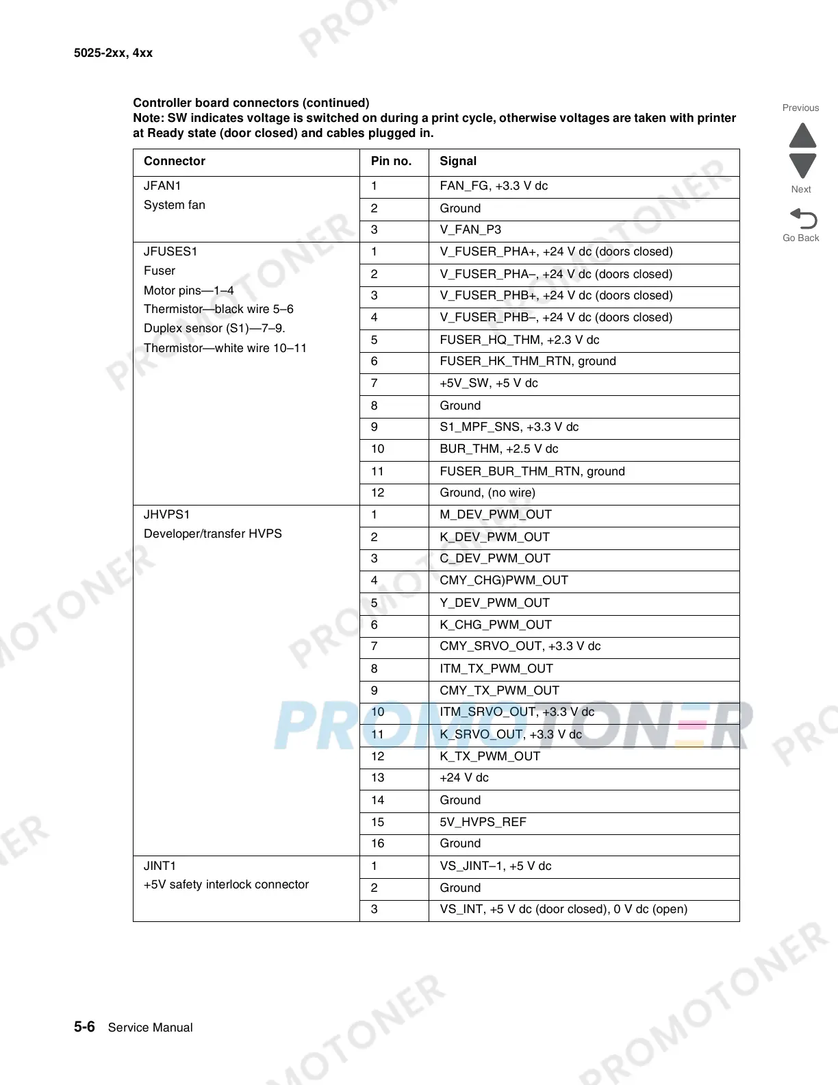
JFAN1
System fan
1 FAN_FG, +3.3 V dc
2 Ground
3V_FAN_P3
JFUSES1
Fuser
Motor pins—1–4
Thermistor—black wire 5–6
Duplex sensor (S1)—7–9.
Thermistor—white wire 10–11
1 V_FUSER_PHA+, +24 V dc (doors closed)
2 V_FUSER_PHA–, +24 V dc (doors closed)
3 V_FUSER_PHB+, +24 V dc (doors closed)
4 V_FUSER_PHB–, +24 V dc (doors closed)
5 FUSER_HQ_THM, +2.3 V dc
6 FUSER_HK_THM_RTN, ground
7 +5V_SW, +5 V dc
8 Ground
9 S1_MPF_SNS, +3.3 V dc
10 BUR_THM, +2.5 V dc
11 FUSER_BUR_THM_RTN, ground
12 Ground, (no wire)
JHVPS1
Developer/transfer HVPS
1 M_DEV_PWM_OUT
2 K_DEV_PWM_OUT
3 C_DEV_PWM_OUT
4 CMY_CHG)PWM_OUT
5 Y_DEV_PWM_OUT
6 K_CHG_PWM_OUT
7 CMY_SRVO_OUT, +3.3 V dc
8 ITM_TX_PWM_OUT
9 CMY_TX_PWM_OUT
10 ITM_SRVO_OUT, +3.3 V dc
11 K_SRVO_OUT, +3.3 V dc
12 K_TX_PWM_OUT
13 +24 V dc
14 Ground
15 5V_HVPS_REF
16 Ground
JINT1
+5V safety interlock connector
1 VS_JINT–1, +5 V dc
2 Ground
3 VS_INT, +5 V dc (door closed), 0 V dc (open)
Controller board connectors (continued)
Note: SW indicates voltage is switched on during a print cycle, otherwise voltages are taken with printer
at Ready state (door closed) and cables plugged in.
Connector Pin no. Signal