5-10 Service Manual
5025-2xx, 4xx
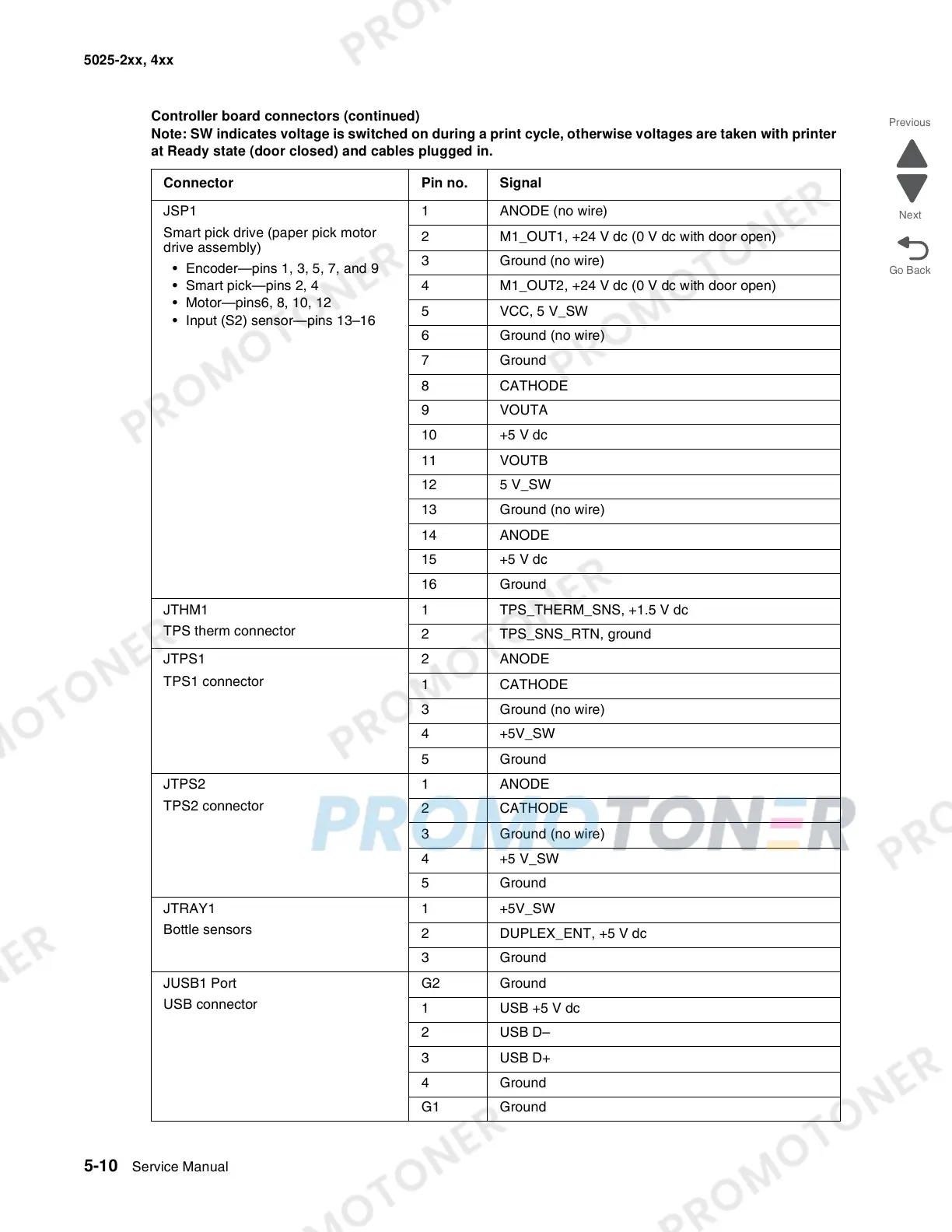
JSP1
Smart pick drive (paper pick motor
drive assembly)
• Encoder—pins 1, 3, 5, 7, and 9
• Smart pick—pins 2, 4
• Motor—pins6, 8, 10, 12
• Input (S2) sensor—pins 13–16
1 ANODE (no wire)
2 M1_OUT1, +24 V dc (0 V dc with door open)
3 Ground (no wire)
4 M1_OUT2, +24 V dc (0 V dc with door open)
5 VCC, 5 V_SW
6 Ground (no wire)
7 Ground
8 CATHODE
9VOUTA
10 +5 V dc
11 VOUTB
12 5 V_SW
13 Ground (no wire)
14 ANODE
15 +5 V dc
16 Ground
JTHM1
TPS therm connector
1 TPS_THERM_SNS, +1.5 V dc
2 TPS_SNS_RTN, ground
JTPS1
TPS1 connector
2 ANODE
1 CATHODE
3 Ground (no wire)
4 +5V_SW
5 Ground
JTPS2
TPS2 connector
1 ANODE
2 CATHODE
3 Ground (no wire)
4+5 V_SW
5 Ground
JTRAY1
Bottle sensors
1 +5V_SW
2 DUPLEX_ENT, +5 V dc
3 Ground
JUSB1 Port
USB connector
G2 Ground
1 USB +5 V dc
2 USB D–
3 USB D+
4 Ground
G1 Ground
Controller board connectors (continued)
Note: SW indicates voltage is switched on during a print cycle, otherwise voltages are taken with printer
at Ready state (door closed) and cables plugged in.
Connector Pin no. Signal