Repair information 4-37
5056-XXX
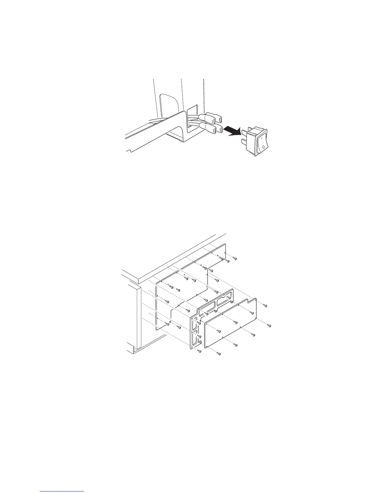
Power switch removal
1. Remove the upper cassette, left front cover, paper feed cover, and left side cover.
2. Unlock the power switch, and pull out the power switch.
3. Remove each terminal connected to the power switch.
Note: When connecting, be careful to connect the connectors correctly. Insert the insulator cover, completely
covering the terminal.
Printer controller removal
1. Open the top unit, and remove the RIP cover, RIP board, RIP box, and electronic box.
2. Remove the connectors and the screws from the printer controller. Pay attention to the location, or label the
two pin connectors when removing them from the board to avoid reconnection into the wrong location.
When replacing the board, install the EPROM (U7) of the former board to the new board. Also, when
replacing the EPROM, set the light intensity in the diagnostic mode, and set the counter and printer
alignment.
Note: After replacing any board on the printer, ensure all the connections are properly connected before closing
the covers.