4-22 Service Manual
4060-xxx
Right side frame
CAUTION: Unplug the printer before you begin.
1. Remove the right side cover. See “Right cover removal” on page 4-10.
2. Remove the laser cover. See “Laser cover removal” on page 4-14.
3. Remove the LVPS. See “Low voltage power supply removal” on page 4-42.
4. Remove the multipurpose tray assembly.
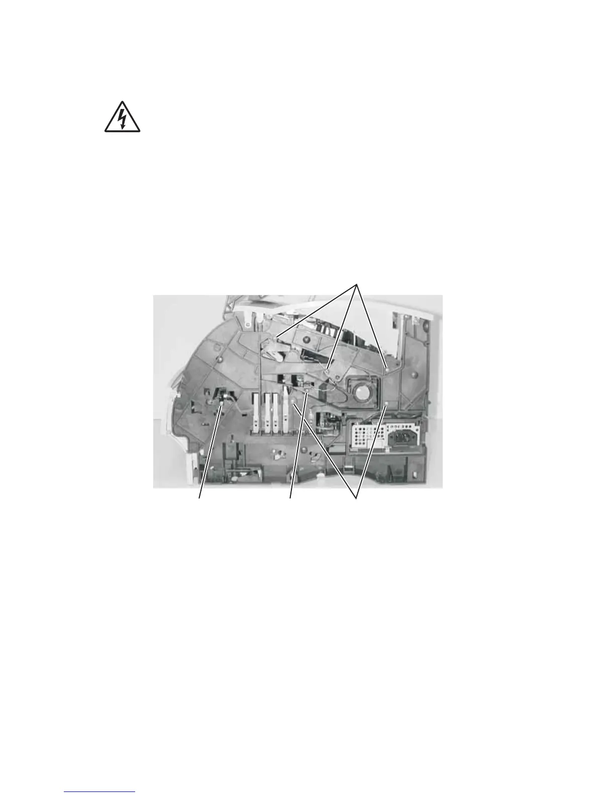
5. Disconnect the autocompensator arm bias spring from the right side frame.
6. Remove the toner sensor mounting screw (A), disconnect the sensor cable and remove the
toner sensor.
7. Remove the smart cartridge contact assembly mounting screw (C)
8. Remove the right side frame mounting screws (B) and remove the right side frame.
CAUTION: Be sure the fuser assembly has cooled before working on any of the fuser FRUs.
A(102) B(102)C
B(102)