Connector locations 5-13
4060-xxx
J13 USB connector J1 G12 Ground
1 USB +5
2 USB MINUS 2
3 USB PLUS 3
4Ground
J1 G2 Ground
J14 Fuser DC 1 NARMEDIA*
2Ground
3 THERM
4Ground
5 THUMP
6 +5V dc
7 THUMPRET
8 EXIT SNS*
J15 Operator Panel 1 OPPAN INT
2Ground
3I2C CLK R
4 +5V dc
5I2C DAT R
J16 (not used)
J17 (not used)
J18 (not used)
J19 Smart cartridge 1 SM Cart
2Ground
3Ground
J20 Parallel port (not used for network model)
J21 (not used)
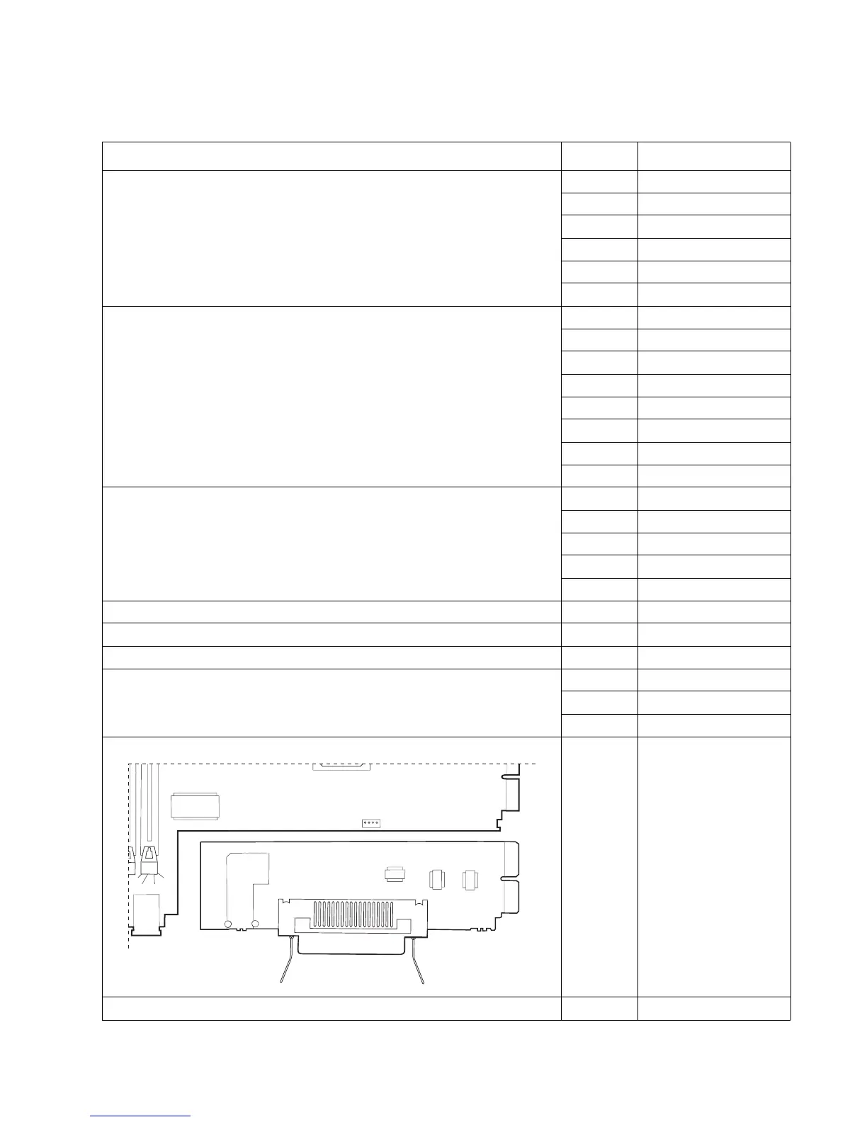
System board—non-network and network (see “System board—non-network” on page 5-10 or “System
board—network” on page 5-11)
Connector Pin no. Signal
99
1
49
100
50
J20
J16
 Loading...