Vertiv | Liebert® GXT5™ | Installer/User Guide 55
Table 4-2 LED Functions
INDICATOR LED COLOR LED STATE INDICATES
Run indicator Green
On UPS output on
Blinking Inverter is starting
O UPS has no output
Alarm indicator
Yellow On Alarm occurs
Red On Fault occurs
None O No alarm, no fault
4.2. LCD Menu and Screens
The menu-driven LCD user interface lets you browse the UPS status, view operating parameters, customize
settings, control operation, and view alarm/event history. Use the function keys to navigate through the menu,
and view statuses or select settings in the screens.
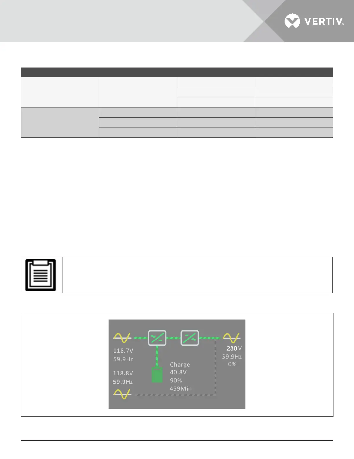
4.2.1. Start-up and Flow Screens
At start-up, the UPS executes a system test and displays the Vertiv logo screen for about 30 seconds, shown
in Figure 4-1 on page 53. After the test completes, an overview screen shows status information, the active
(green) power path, and the inactive power path (gray).
• Figure 4-3 is an example flow screen and does not reflect the actual values that you may see on your
unit.
Figure 4-3 UPS Flow Screen