EasyManuals Logo

Liebert Vertiv GXT5 User Manual

Liebert Vertiv GXT5
136 pages
To Next Page IconTo Next Page
To Previous Page IconTo Previous Page
Page #97 background imageLoading...
Page #97 background image
Vertiv | Liebert® GXT5™ | Installer/User Guide 89
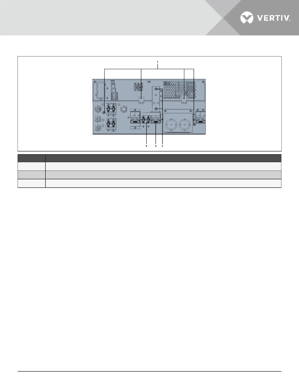
Figure 5-3 Maintenance-bypass Breaker Cover and Captive Screws
ITEM DESCRIPTION
1 Captive screws for POD
2 Connector-cover screws
3 Maintenance-bypass breaker
5.6. Firmware Updates
The UPS has two rmware components:
DSP is the rmware for the power module.
MCU is the rmware for the display panel.
Both
may be updated through a connection the UPS, using CLI method via connecting the RS232 port on the rear
of the UPS, if the UPS includes the IntelliSlot RDU101 card, using the RJ-45 port on the card.
The latest rmware is available for download from the GXT5 product page at www.Vertiv.com. Refer to Table 5-2
below, and make sure you have the correct les for the update.

Table of Contents

Questions and Answers:

Question and Answer IconNeed help?

Do you have a question about the Liebert Vertiv GXT5 and is the answer not in the manual?

Liebert Vertiv GXT5 Specifications

General IconGeneral
Output Voltage230V
TopologyDouble Conversion Online
Frequency50/60 Hz
Operating Temperature0°C to 40°C
DimensionsVaries by model
WeightVaries by model
Form FactorRack/Tower
Battery TypeValve Regulated Lead Acid (VRLA)
Communication PortsUSB, RS-232
EfficiencyUp to 95%
Typical Recharge Time3 hours to 90%
Storage Temperature-15°C to 40°C
Humidity0% to 95% non-condensing

Related product manuals