Page 24 of 295
Drawings
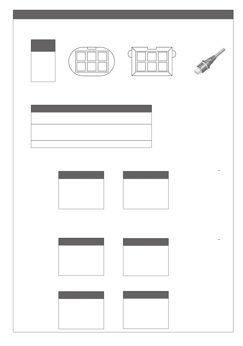
Figure 6
LA23/LA31/LA34/BL1/BL4 Mini-fit plug cable
Pin 1
Pin 2
Pin 3
Pin 4
Pin 5
Pin 6
EOS Switch
Switch com. (GND)
Vbus
M+ (Motor/Power)
EOS out
EOD in
M- (Motor/Power)
without Feedback
EOS Switch
Switch com. (GND)
Vbus
M+ (Motor/Power)
EOS wout
EOD in
M- (Motor/Power)
without Feedback
Mini-Fit
Connector
Pin 1
Pin 2
Pin 3
Pin 4
Pin 5
Pin 6
4
5
6
1 2 3
Connector front view
6
5 4
3 2 1
PCBA Header top view
13) Pin-connection for Mini-fit plug (valid for 13 and 14)
Hall
Hall com. (GND)
Vbus
M+ (Motor/Power)
EOS (analog)
Hall
M- (Motor/Power)
with Feedback
Hall
Hall GND
Vbus
M+ (Motor/Power)
Hall A
Hall B
M- (Motor/Power)
with Feedback
Pin 1
Pin 2
Pin 3
Pin 4
Pin 5
Pin 6
CH1-4 MiniFit:
When a channel is operated UP
3: Brown: +
(Motor connections)
6: Yellow: -
5: Orange: UP
End-of-stroke switches
4: Red: DOWN
2: Black: COMMON
Not Used
1: No Connection
(end of stroke = EOS)
WITHOUT FEEDBACK
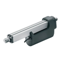
LA27 Mini-fit plug cable (LA27 standard; Valid for LA27 article numbers = 27xxxxxxxxxxxx0)
LA27 Mini-fit plug cable (Analog encoded without Hall)
Article numbers = 27xxxxxxxxxxxxB
LA23/LA31/LA34/LA44/BL1 Mini-fit plug cable
LA27 Mini-fit plug cable
WITH FEEDBACK
Reed
Reed com. (GND)
Vbus
M+ (Motor/Power)
NC
Reed
M- (Motor/Power)
Potentiometer
Pot GND
Vbus
M+ (Motor/Power)
Pot Position
Pot + (3V3)
M- (Motor/Power)
Pin 1
Pin 2
Pin 3
Pin 4
Pin 5
Pin 6
LA34/LA44 Mini-fit plug cable (potentiometer) BL4 Mini-fit plug cable
Article numbers = 27xxxxxxxxxxxxA
0273011 with O-ring