Page 31 of 295
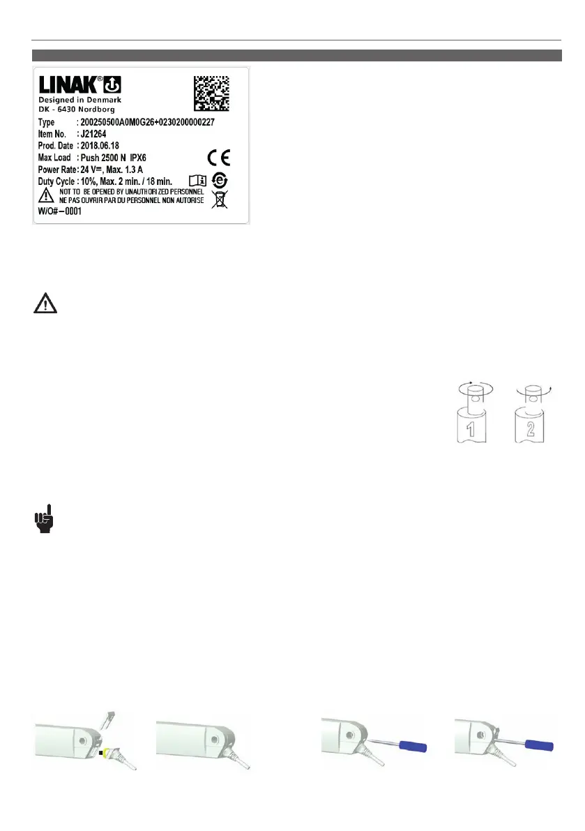
3. Information on specific actuators
LA20 is a slim inline actuator created to cover a wide range of applications, where
design, size and power are crucial. The combination of a high lifting capacity of 2,500 N
with its robust but stylish, small form factor makes the LA20 the ideal solution for many
of today’s demanding applications.
1. LA20 Inline (MEDLINE
®
CARELINE
®
)
Usage
• Duty cycle: Max. 10 %, 2 minutes continuous use followed by 18 minutes not in use
• Usage temperature: +5 ºC to +45 ºC normal operating temp.
-27 ºC to +50 ºC (according to test conditions ISO 7176-9)
• Storage temperature: -40 ºC to +70 ºC (according to ISO 7176-9)
• Compatibility: Compatible with LINAK control boxes. Please contact LINAK
• Relative humidity: 20% to 80% - non-condensing
• Approvals: IEC60601-1, ANSI/AAMI ES60601-1,
CAN/CSA-C22.2 No. 60601-1
In compliance with ISO 7176-8
• Atmospheric pressure: 700 to 1060 hPa
• Meters above sea level: Max. 3000 meters
• Cycles: The LA20 life cycle test has been performed with a stabilised power supply
(10% duty cycle) on a 120 mm stroke actuator at max. load for 10,000 cycles
(at ambient temperature)
• Flammability rating: UL94-V0
Warnings
• Do not sideload the actuator
• Only use the actuator within specified working limits
• When mounting the LA20 in the application ensure that the bolts can withstand the wear and they are secured safely
• Motor type G and B must only be used with their respective control box types.
• Motor type B: motor which must be used with COBO, CBJC, CBJ1, CBJ2, CBJH or generally in applications that are mainly battery driven or customers’
own control box.
• Motor type G: motor which must be used with CO61, CO71, CO41, CA30/40.
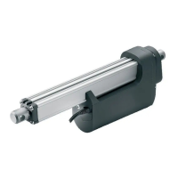
• Instruction concerning the turning of the piston rod eye: When mounting and taking into use, it is not permitted
to make excessive turns of the piston rod eye. In cases where the eye is not positioned correctly, it is permitted
to first screw the eye down to its bottom position, at a maximum torque of 2 Nm (1), and thereafter a
maximum half turn outwards again (2).
• If an actuator with stroke length below 50 mm is used, and the electrical endstop switch fails, be aware that the distance before reaching the
mechanical endstop will be prolonged.
The extra distance will be 50 mm minus the actual stroke length.
This means that an actuator with 20 mm stroke length will travel an additional 30 mm before reaching the mechanical endstop if the switch fails.
Recommendations
• Do not place load on the actuator housing and do prevent impact or blows or any other form of stress to the housing
• Connection bolts must be dimensioned so that they have the necessary strength and tolerance in order to obtain the minimum safety factor according
to the requirements of the authorities
• Ensure that the cable lock is mounted correctly
• Ensure that the cable cannot be squeezed, pulled or subjected to any other stress
• Only use the actuator within the specifications
• Connection bolts and brackets are to be inspected in connection with service and must be replaced if there are signs of wear
• The product must always have the motor short circuited to obtain self-locking according to label value/rated value
• Ensure that the duty cycles and the usage temperatures for LA20 actuators are respected
• The LA20 is not suitable for use in outdoor applications where it can be exposed to sun and rain.
• Do not expose the actuator to pull during transport of the application
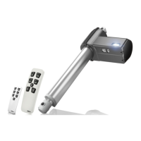
Cable mounting
A: To mount a cable
Step 1:
Place a screwdriver in the hole in
the back ficture of the actuator
Step 1:
Place the cable in the actuator
Step 2:
Press the cable lock down into place
B: To remove/change a cable
Step 2:
Push to remove the cable lock
an remove/change the cable