Page 39 of 96
© 2020 LINAK A/S
Actuator with IC Basic
I/O specifications:
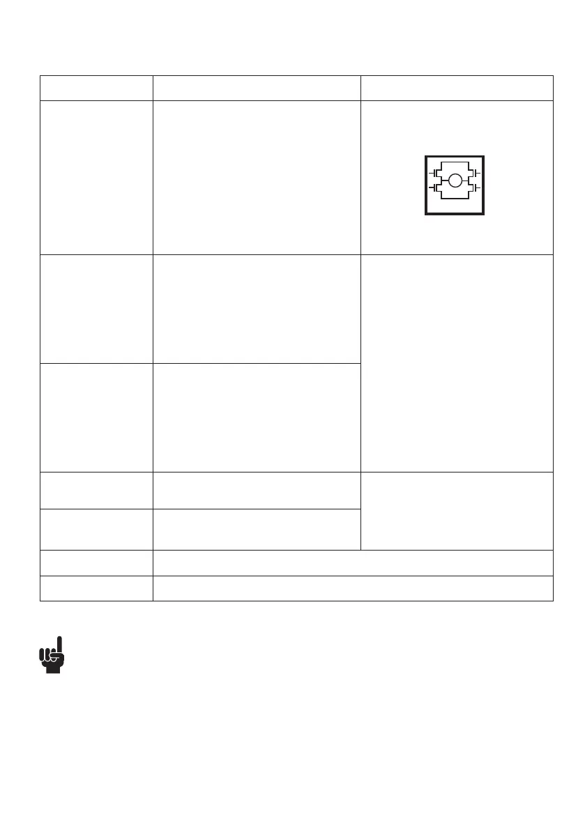
Input/Output Specification Comments
Description Easy to use interface with integrated
power electronics (H-bridge).
The actuator can also be equipped with
electronic circuit that gives an absolute or
relative feedback signal.
The version with “IC option” cannot be
operated with PWM (power supply).
See connection diagram,
fig. 13, page 39
Brown 12-24VDC + (VCC)
Connect Brown to positive
12V ± 20%
24V ± 10%
12V, current limit 30A
24V, current limit 20A
Note: Do not change the power supply
polarity on the brown and blue wires!
Power supply GND (-) is electrically
connected to the housing
If the temperature drops below 0°C,
all current limits will automatically
increase to 30A for 12 V and 25 A for
24 V
Blue 12-24VDC - (GND)
Connect Blue to negative
12V ± 20%
24V ± 10%
12V, current limit 30A
24V, current limit 20A
Red Extends the actuator On/off voltages:
> 67% of V
IN
= ON
< 33% of V
IN
= OFF
Input current: 10mA
Black Retracts the actuator
Green Not to be connected
Yellow Not to be connected
M
H-Bridge
• Current cut-offs should not be used as stop function! This might damage the actuator. Current cut-
offs should only be used in emergencies!
• Current cut-off limits are not proportional with the load curves of the actuator. This means that the
current cut-offs cannot be used as load indicator.
• There are tolerances on the spindle, nut, gear wheels etc. and these tolerances will have an
influence on the current consumption for the specific actuator.