9.4.3 Read Holding Registers (03)
(1) Reading word of output area
When reading data of word type of output area, request and response frame is as follows.
Tail of frame is applied in case of ASCII mode.
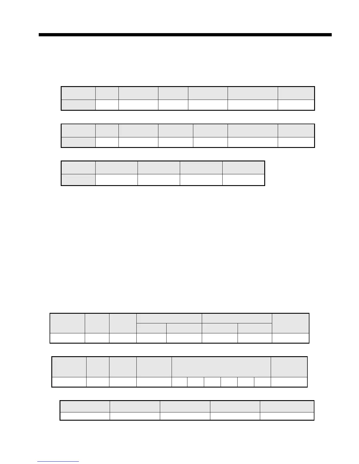
(a) Request frame
Classification
No. of byte Data Frame error check Tail (CRLF)
Size (Byte) 1 1 2 N*2 2 2
(c) Response frame (When receiving abnormal frame)
Classification Station no. Error code
Tail (CRLF)
Size (byte) 1 1 1 2
(2) Details of frame
(a) Station no.: indicates the station no. of slave to read word data of output area.
(b) Function code: ‘03’ indicating Read Holding Registers
(c) Address: indicating start address of data to read. It consists of 2 byte. At this time, start address conforms
to modbus address regulation.
(d) Data size: size of data to read, consists of 2 byte
(e) Frame error check: in case of ASCII mode, it uses LRC and in case of STU mode, it uses CRC for error
check. It consists of 2 byte.
(f) Tail: it is applied in case of ASCII mode, CRLF is added after LRC.
(g) No. of byte: no. of byte of data responding
(h) Data: address of request frame is start address and transmits data with byte unit. At this time, since data is
word type, it is double of no. of byte.
(i) Error code: error code is expressed by adding 80(Hex) and in case of reading word of output area, it is
expressed 83(Hex).
(j) Exceptional code: details of error, consists of 1 byte.
(3) Frame example
Example that reads word (108~110) from station number 1 server acting as modbus RTU
(a) Request frame
Classification
Station
no.
Function
code
Address Data size
Error check
Upper byte Lower byte Upper byte Lower byte
Frame 01 03 00 6B 00 03 CRC
(b) Response frame (receiving normal frame)
Classification
Station
no.
Function
code
No. of byte Data Error check
Frame 01 03 06 13 12 3D 12 40 4F CRC
(c) Response frame (receiving abnormal frame)
Classification Station no. Function code Exceptional code Error check