Chapter 2 specification
2-5
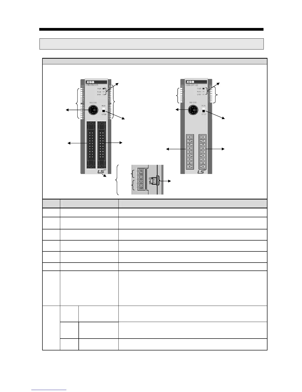
2.3 Name and Function of each part
XBM “S” Type
No. Name Purpose
①
Input indication LED Input indication LED
②
PADT connection
connector
PADT connection connector
③
Input connector and
terminal block
Input connector and terminal block
④
Output connector and
terminal block
Output connector and terminal block
⑤
Key switch
RUN / STOP key switch
- In case key switch is STOP, remote mode change available
⑥ Output indication LED Output indication LED
⑦
Status indication LED
Indicates operation status of CPU module
- PWR(Red): Power status indication
- RUN(Green): RUN status indication
STOP mode: Off / RUN mode : On
- Error(Red): Flicker in case error occurs
⑧
8-1
Built-in RS-485
Connection
connector
Built-in RS-485 connection connector
- “+”, “-“ terminal connection connector ofRS-485 communication
8-2
Built-in RS-232C
connection
connector
Built-in RS-232C connection connector
-“TD”, “RD”, “SG” terminal connection connector of RS-232C
communication
8-3 Power connector DC24V power connector
①
②
④
⑤
⑥
③
⑦
③
⑧
8-1
8-2
④
①
②
⑤
⑥
⑦
XBM-DR16S
XBM-DN16/32S
8-3