Chapter 12 Installation and Wiring
12 −20
12.5.2 RS-422/485 interface (Built-in communication)
Built-in communication channel (RS-232C/RS-485) uses 5-pin connector (Terminal Block) for
communication with external devices. The names and functions of pins and data directions are as
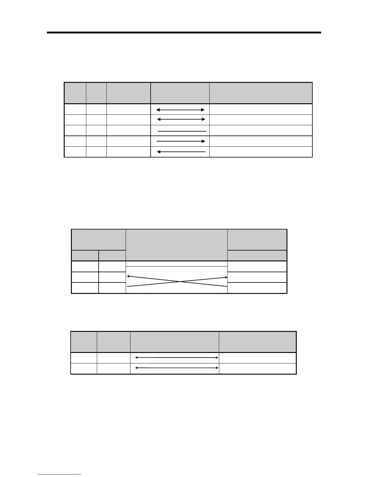
shown in [Figure 12.5.4] below
Pin no. Name Content
Built-in RS-232C TX data signal
Built-in RS-232C RX data signal
[Figure 12.5.4] RS-422 5-pin Connector Standard
Built-in RS-232C channel doesn’t support modem communication. In case of modem communication,
use XBC-C21A.
1) Connection method in case of using built-in RS-232C
In case of connecting as null modem mode, connect in 3 line type.
Cnet (9-PIN)
Connection no. and signal direction
PC/Communication
[Figure 12.5.5] 3 line type connection
2) Connection method in case of using built-in RS-485
Pin no. Name
Signal direction
(Cnet<--->external device)
[Figure 12.5.6] built-in RS-485 connection