9.4 Modbus Protocol
9.4.1 Reading data of bit type at the bit output (01)
(1) Reading bit of output area (function code: 01)
In case of reading data of bit type, request and response frame is as follows.
Detail of frame is applied in case of ASCII mode.
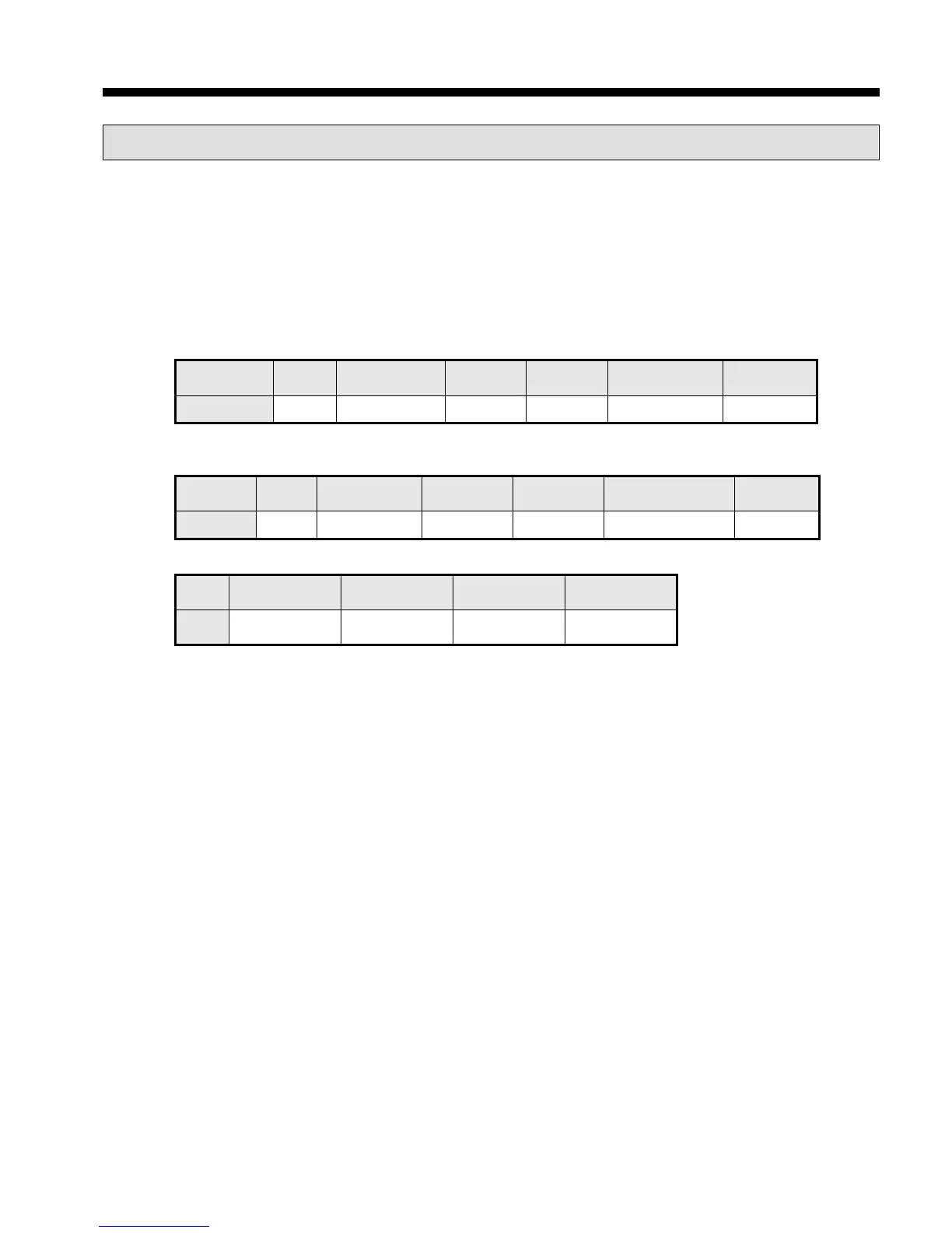
(a) Request frame
Frame
No. of byte Data Frame error check Tail (CRLF)
Size (byte) 1 1 2 N 2 2
(c) In case of response frame (In case of receiving abnormal frame)
Frame Station no. Error code
1 1 1 2
(2) Details of frame
(a) Station no.: indicates the station no. of slave to read bit of output area.
(b) Function code: ‘01’ indicating Read Coil Status
(c) Address: start address of data to read and it consists of 2 byte. At this time, start address conforms to
modbus address regulation.
(d) Data size: size of data to read and it consists of 2 byte.
(e) Frame error check: in case of ASCII mode, it uses LRC and in case of STU mode, it uses CRC. It
consists of 2 byte.
(f) Tail: it is applies in case of ASCII mode, CRLF is added after LRC.
(g) No. of byte: no. of byte of response data
(h) Data: makes address of request frame as start address and transmits data with byte unit
(i) Error code: error code is expressed by adding 80(Hex) to function code and in case of reading bit of
output area, it is expressed as 81(Hex).
(j) Exceptional code: indicates detail of error and consists of 1 byte