9.4.5 Force Single Coil (05)
(1) Writing single bit of output area
When writing single bit of output area, request and response frame is as follows.
Tail of frame is applied in case of ASCII mode.
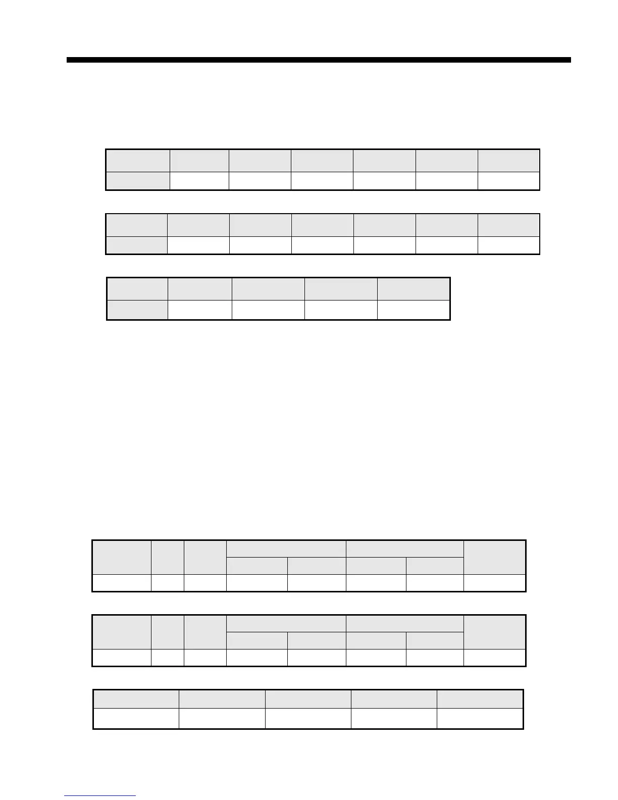
(a) Request frame
Classification Station no.
Tail (CRLF)
Size (byte) 1 1 1 2
(2) Details of frame
(a) Station no.: indicates the station no. of slave to write single bit of output area.
(b) Function code: ‘05’ indicating Force Single Coil
(c) Address: start address of data to write and it consists of 2 byte. At this time, start address conforms to
modbus address regulation.
(d) Output: in case of turning on address set in the Address, FF00(Hex) is indicated and in case of turning off
addres set in the Address, it is indicated 0000(Hex).
(e) Frame error check: in case of ASCII mode, it uses LRC and in case of STU mode, it uses CRC. It
consists of 2 byte.
(f) Tail: it is applies in case of ASCII mode, CRLF is added after LRC.
(g) No. of byte: no. of byte of response data
(h) Error code: error code is expressed by adding 80(Hex) to function code and in case of Force Single Coil,
it is expressed as 85(Hex).
(i) Exceptional code: indicates detail of error and consists of 1 byte
(3) Frame example
Example that turning on 9
th
bit to station number 1 server acting as Modbus RTU mode
(a) Request frame
Classificatio
n
Statio
n no.
Function
code
Address Output
Error check
Upper byte Lower byte Upper byte Lower byte
Frame 01 05 00 08 FF 00 CRC
(b) Response frame (In case receiving normal frame)
Classificatio
n
Statio
n no.
Function
code
Address Output
Error check
Upper byte Lower byte Upper byte Lower byte
Frame 01 05 00 08 FF 00 CRC
(c) Response frame (In case of receiving abnormal frame)
Classification Station no. Function code Exceptional code Error check
Frame 01 85 04 CRC