Chapter 8 LS Bus Protocol
8.2 Detail of instruction
8.2.1 Continuous writing to inverter device (W)
This command is to write PLC data in specified address of inverter.
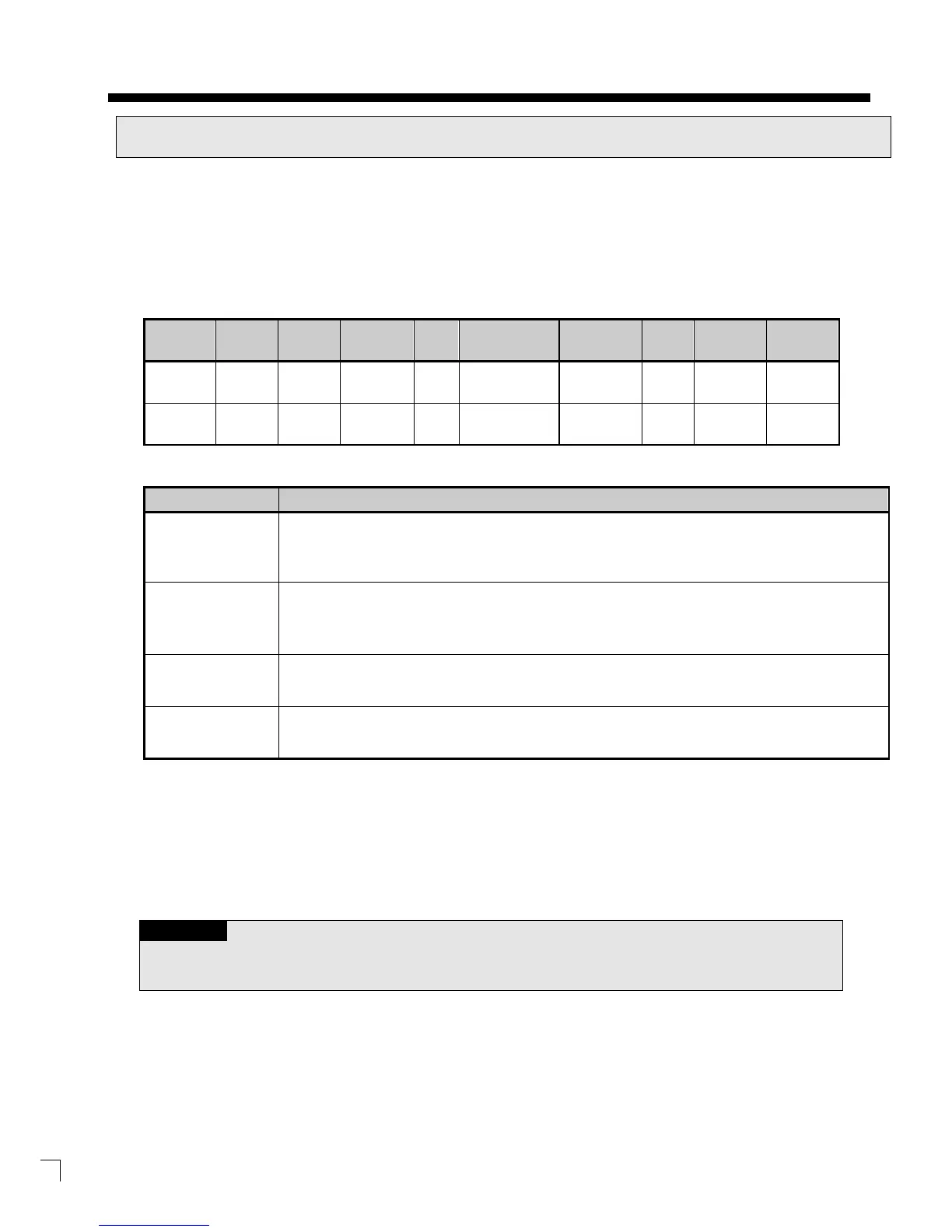
LS Bus Client Request format
Format
ENQ H20 W H6 0100 H00E2 - BCC EOT
H05 H3230 H57 H36 H30313030 H30304532 - - H04
Item Description
BCC
When ASCII value of each 1byte except ENQ and EOT is summed, the lowest 1byte of the result
value is BCC.
Device
Length
This specifies how many Words you will write.
As converted value to ASCII, the range is from H01
(ASCII value: 3031) to H08 (ASCII value: 3038).
Address of inverter
Enter the address that you want to read. ASCII value above 4 characters and non-
allowed.
Data When you write data H'A to inverter address 0100 area, the data format has to be H000A.
Example)
If you want to write H1234, 31323334 (Converted value to ASCII) should be included in the data area. So, the
highest value has to be sent first and the lowest value has to be sent last.
• Device data of Word type is only supported.