215626 14 Revision A
5
3
$
%
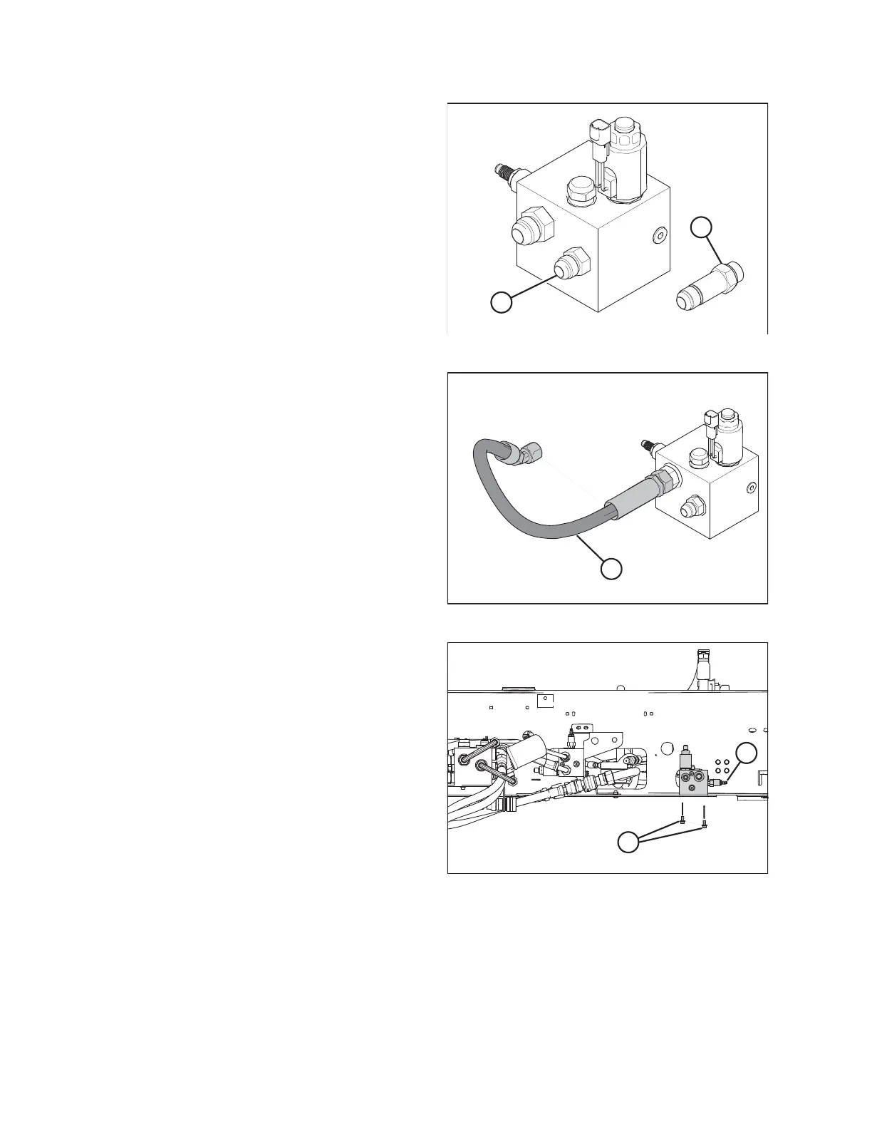
Figure 2.5: DWA Drive Manifold
3. Select the correct fitting for your windrower model:
• For M150/M200: Install #10 ORB x #10 JIC fitting (A) in
the P port on the DWA drive manifold.
• For M155/M155E4/M205: Install long #10 ORB x #10
JIC fitting (B) in the P port on the DWA drive manifold.
5
3
$
Figure 2.6: DWA Drive Manifold
4. To simplify assembly, attach hose (A) to the fitting in the R2
port of the DWA drive manifold before attaching the
manifold to the frame.
$
%
Figure 2.7: Windrower Left Side – M205 Shown
5. Attach the DWA drive manifold to the windrower left side
frame with two 3/8 in. serrated flange bolts (A). Route the
hose and fittings through the side frame so that they point
toward the windrower engine and relief valve (B) points
toward the rear of the windrower.
NOTE:
Leave the plugs in ports DWA and R1.
SETUP INSTRUCTIONS