215626 15 Revision A
Figure 2.8: M150/M200 Configuration after Installing
the DWA Drive Manifold
A - Hose B - Bypass Relief Valve
C - Hose D - Supercharge Pump
P - Port P
6. Remove hose (A) from cooler bypass relief valve (B) and
connect it to the fitting at the P port on the DWA drive
manifold. The other end of hose (A) is connected to
supercharge pump (D).
7. Install the other end of hose (C) to cooler bypass relief
valve (B) where hose (A) was removed.
NOTE:
Gain access to hose (A) from under the windrower or by
raising the windrower hood and working from the left
platform.
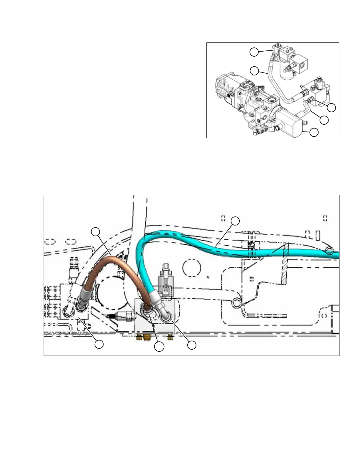
Figure 2.9: M205 Hose Configuration
A - Hose from Port P on DWA Drive Manifold to Pump (not visible) B - Cooler Bypass Relief Valve
C - Hose from Port R2 on DWA Drive Manifold to Cooler Bypass Relief Valve P - Port P
SETUP INSTRUCTIONS