215626 23 Revision A
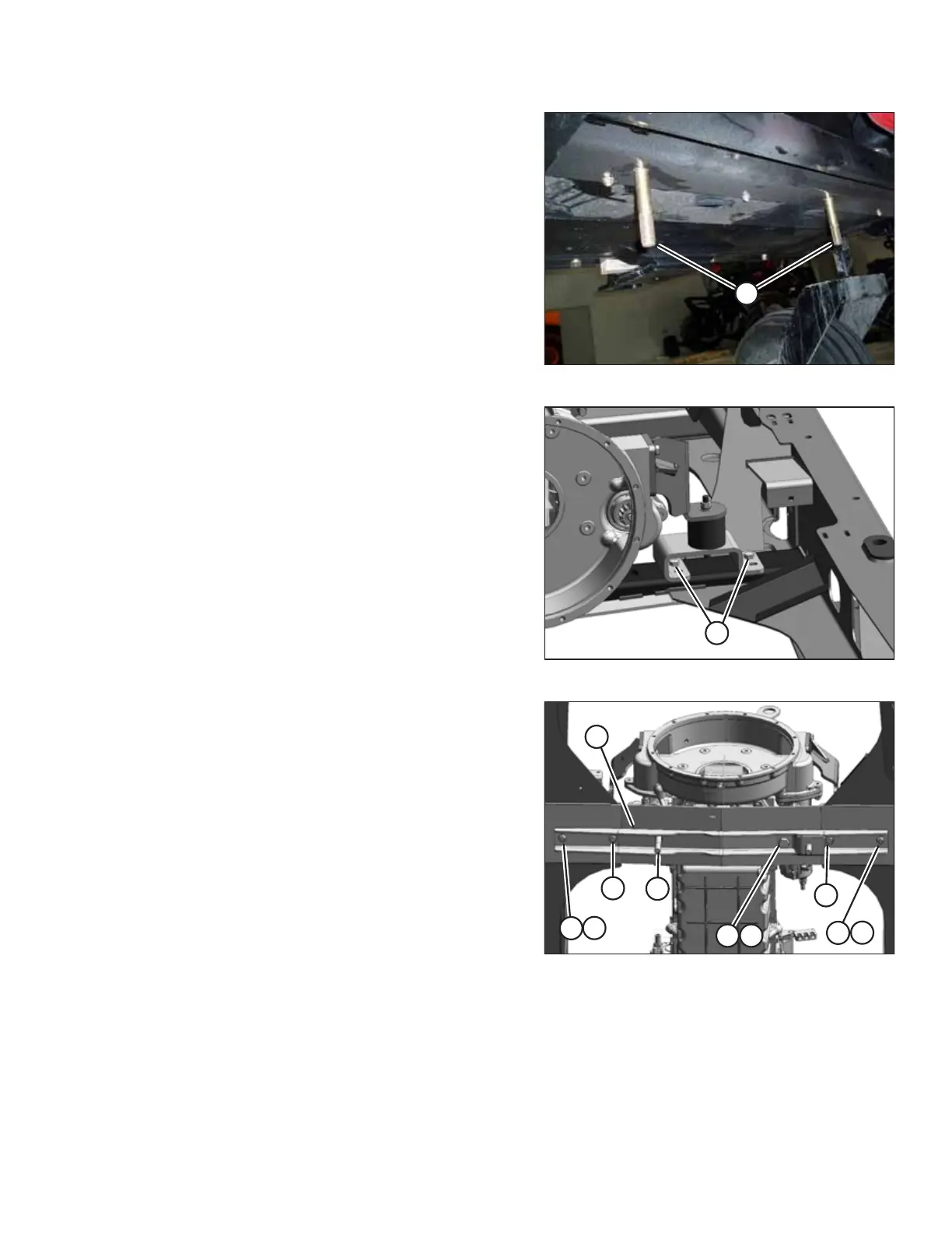
Figure 2.27: Windrower Frame Member
2. Install two 3/4 in. x 4 1/2 in. long carriage head bolts (A) in
the windrower frame member located between the engine
and the caster wheels.
NOTE:
Move the hoses located above the frame member in order
to install the bolts.
Figure 2.28: Windrower Engine Mount
3. Remove four bolts (A) from the front engine mounts (two
on the left side and two on the right side). Retain the nuts.
Figure 2.29: Linkage Support
4. Mount support (A) to the windrower frame with four
1/2 in. x 2 3/4 in. hex head bolts (C) with flat washers under
the bolt heads. Secure the bolts with nuts (B).
NOTE:
These bolts replace the engine mount bolts removed in
Step 3, page 23.
5. From below the support, install 3/4 in. x 3 1/2 in. long hex
head bolt (E) with flat washer (F) under the bolt head.
6. Secure the bolt with a flat washer, a lock washer, and a nut
on the top side of the frame.
7. From above the support, install 3/4 in. x 5 1/2 in. long hex
head bolt (D) with flat washer under the bolt head. Do NOT
install a nut on bolt (D).
SETUP INSTRUCTIONS