5-60 Published 7-23-2020, Control # 668-02
SET-UP AND INSTALLATION GRT9165 OPERATOR MANUAL
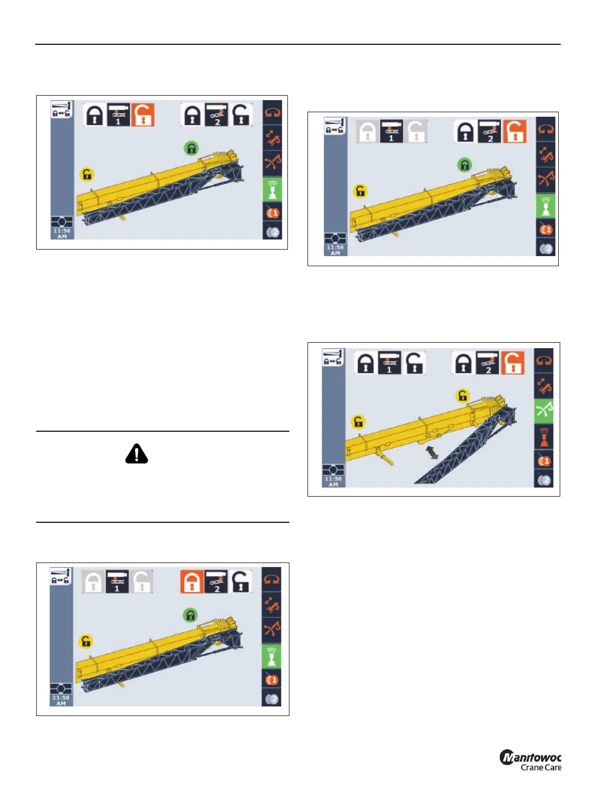
The lock status icon turns yellow, indicating the pin
is retracted.
12. Visually confirm that the rear mounting pin (Pin #1 in the
ODM) is unlocked.
13. Using the tag line, swing the boom extension on to the
rear ramp so the boom extension installation pins (4,
Figure 5-40) align with the holes in the main boom
attachment fittings (2).
14. With an impact wrench and 14 mm socket extension,
turn the jack screw (3, Figure 5-40) counterclockwise to
extend the boom extension installation pins (4) into the
boom nose attachment fittings (2). The jack screw drive
will bottom out when the pins are fully engaged. Verify
that the pins (4) are fully engaged and that the bolts and
washers are at the end of the slots.
15. In the ODM, retract the front mounting pin (Pin #2) as
follows:
a. Use the ODM control pad arrow buttons or jog dial
to highlight unlock icon.
The unlock icon is highlighted (orange).
b. Press and hold the OK on the ODM control pad or
press down on the jog dial.
The lock status icon turns yellow, indicating the pin
is retracted. The boom extension is displayed as
detached from the side of the main boom.
16. Visually confirm that the front mounting pin (Pin #2 in the
ODM) is unlocked. The handle should be in the down
position. When the handle is in the down position, the
front mounting pin is retracted and the boom installation
pins are locked.
NOTE: The front mounting pin (Pin #2) will not unlock
unless the right side boom extension installation
pins are fully engaged. If the front boom extension
pin (Pin #2) does not unlock, make sure the right
side boom extension installation pins are fully
engaged and the cable ends are inserted through
the pins.
DANGER
Crush Hazard
To avoid death or serious injury, ensure boom extension
installation pins (4, Figure 5-40) are installed prior to
retracting the front mounting pin (Pin #2).

 Loading...


