Grove Published 7-23-2020, Control # 668-02 5-59
GRT9165 OPERATOR MANUAL SET-UP AND INSTALLATION
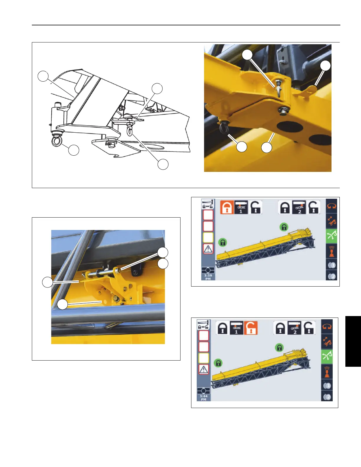
10. Remove retaining clip and pin (1 and 2, Figure 5-46)
from holes in the fly section stowage bracket (3). Install
the retaining clip and pin in the storage position (4).
11. In the ODM, highlight the unlock icon and the retract the
rear boom extension pin (Pin #1) as follows:
a. Use the ODM control pad arrow buttons or jog dial
to highlight unlock icon.
The unlock icon is highlighted (orange).
b. Press and hold the OK on the ODM control pad or
press down on the jog dial.
FIGURE 5-45
4
Deployed
Stowed
1
2
3
1
2
3
4
9988
9989

 Loading...


