5-68 Published 7-23-2020, Control # 668-02
SET-UP AND INSTALLATION GRT9165 OPERATOR MANUAL
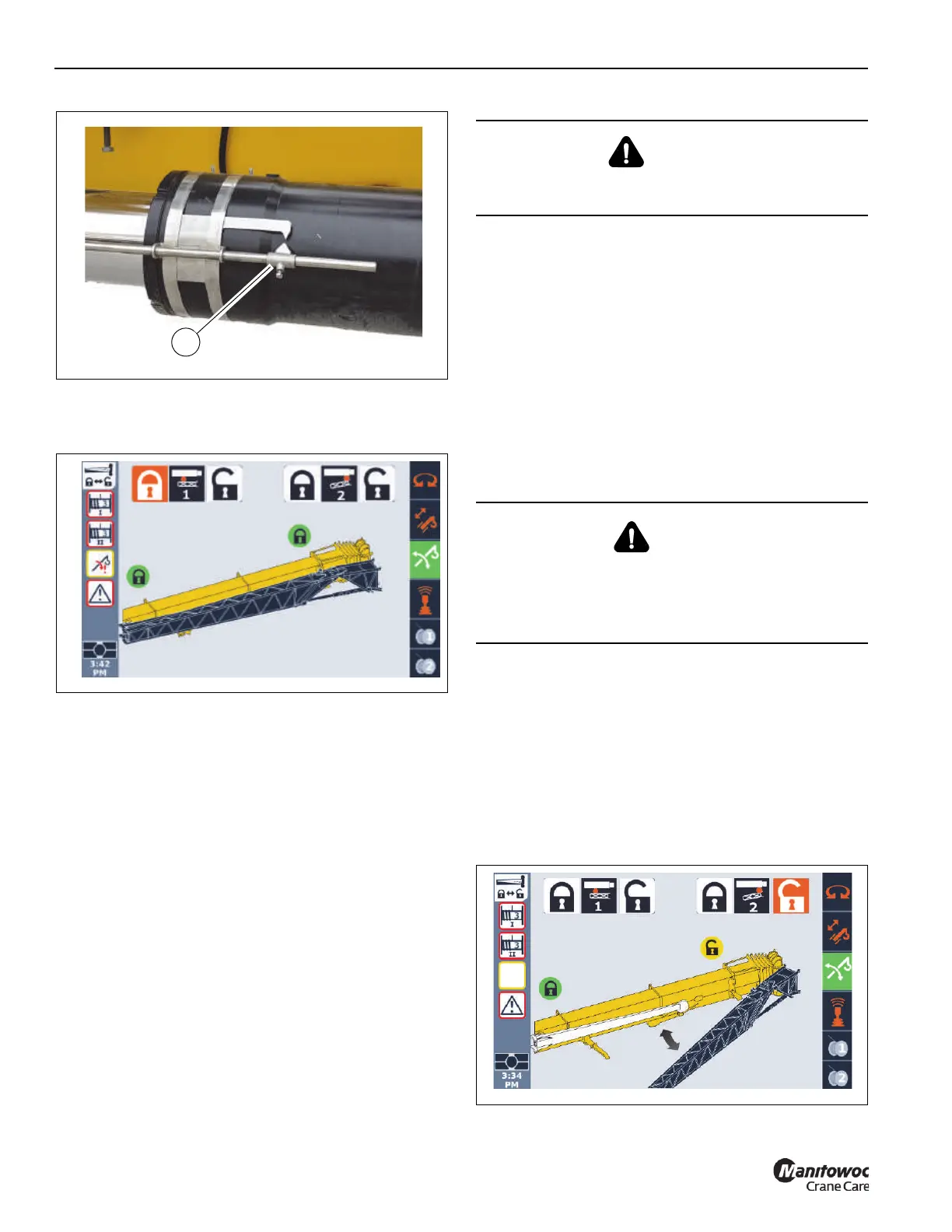
6. In the ODM, verify that the front (Pin #2) and rear (Pin
#1) boom extension pins are securely installed. Visually
confirm that the pins are installed.
7. Tie a tag line (1, Figure 5-37) to the end of the boom
extension base section (2). The tag line will assist when
swinging the boom extension to the boom nose.
8. Remove the retaining clip (1, Figure 5-51) and pin (2)
from the boom extension fly section (4). Remove the
locking bar (3) from the boom extension fly section (4).
Rotate the locking bar (3) and store the clip and pin in
retaining bracket (5) on the boom extension base
section (6).
9. Remove pin (1, Figure 5-45) and retaining clip (2) and
deploy the rear boom extension ramp (3). Insert pin and
retaining clip to secure the ramp.
10. Visually confirm the rear boom extension pin (Pin #1 in
the ODM) (2, Figure 5-32) properly secures the fly
section to the main boom. Visually confirm the fly section
is securely stowed on the fly section stowage bracket (3,
Figure 5-46).
11. Remove retaining clips (9, Figure 5-52) and pins (10) to
decouple the boom extension base section from the fly
section.
12. Using the tag line, swing the boom extension out on the
rear ramp to the intermediate position so the boom
extension anchor fittings (1, Figure 5-40) engage with
the main boom attachment fittings (2).
13. Align the holes for the boom installation pins. With an
impact wrench and extension, turn the jack screw (3)
extend the boom installation pins (4) into the boom nose
attachment fittings (2). The jack screw drive will bottom
out when the pins are fully engaged. Visually confirm
that the pins (4) are fully engaged.
14. In the ODM, highlight the front boom extension pin (Pin
#2) unlock icon and retract Pin #2 as follows:
a. Use the ODM control pad arrow buttons or jog dial
to highlight unlock icon.
The unlock icon is highlighted (orange).
b. Press and hold the OK on the ODM control pad or
press down on the jog dial.
The lock status indicator icon turns yellow,
indicating Pin #2 is retracted.
CAUTION
After removing the four retaining clips and pins, the boom
extension is free to swing to the side of the main boom.
DANGER
Crush Hazard
To avoid death or serious injury, make sure boom
extension installation pins (4, Figure 5-40) are installed
prior to retracting the front mounting pin (Pin #2).

 Loading...


