OPERATING CONTROLS AND PROCEDURES RT9130E-2 OPERATOR MANUAL
3-10 Published 3-1-2018, Control # 559-03
Hoist Rotation Indicator Display
The display is located in the front overhead panel
Figure 3-10.
Refer to Hoist Rotation Indicators (HRI), page 3-19 for more
information.
Exhaust System Cleaning Switch (Tier 4
Engines Only)
The Engine Exhaust System Cleaning Switch (9, Figure 3-4)
is located on the right side of the overhead control panel.
This switch is a three position switch, Inhibit Cleaning/Permit
Active Cleaning/Initiate Manual Cleaning. Center position
enables clean to occur when required, or press this switch to
force manual cleaning to begin immediately or to disable
cleaning indefinitely:
• Manual Cleaning
(7649-10)
• Inhibit Cleaning (7649-11)
To manually clean, set the crane parking brake, the crane
transmission must be in neutral and have the brake and
throttle pedals released.
Refer to Exhaust System Cleaning (Tier 4 Engines Only),
page 3-14 for cleaning mode definitions and a description of
when manual cleaning is needed.
Set up a safe area around the crane’s exhaust; remove tools,
rags, grease or any debris from the engine exhaust area.
With the engine idling push the Cleaning Switch (9) to the
Manual Clean position to initiate manual cleaning.
Within 5 seconds the engine should rev up to 1000 to 1400
rpm. The engine will continue to run at this speed for up to 45
minutes.
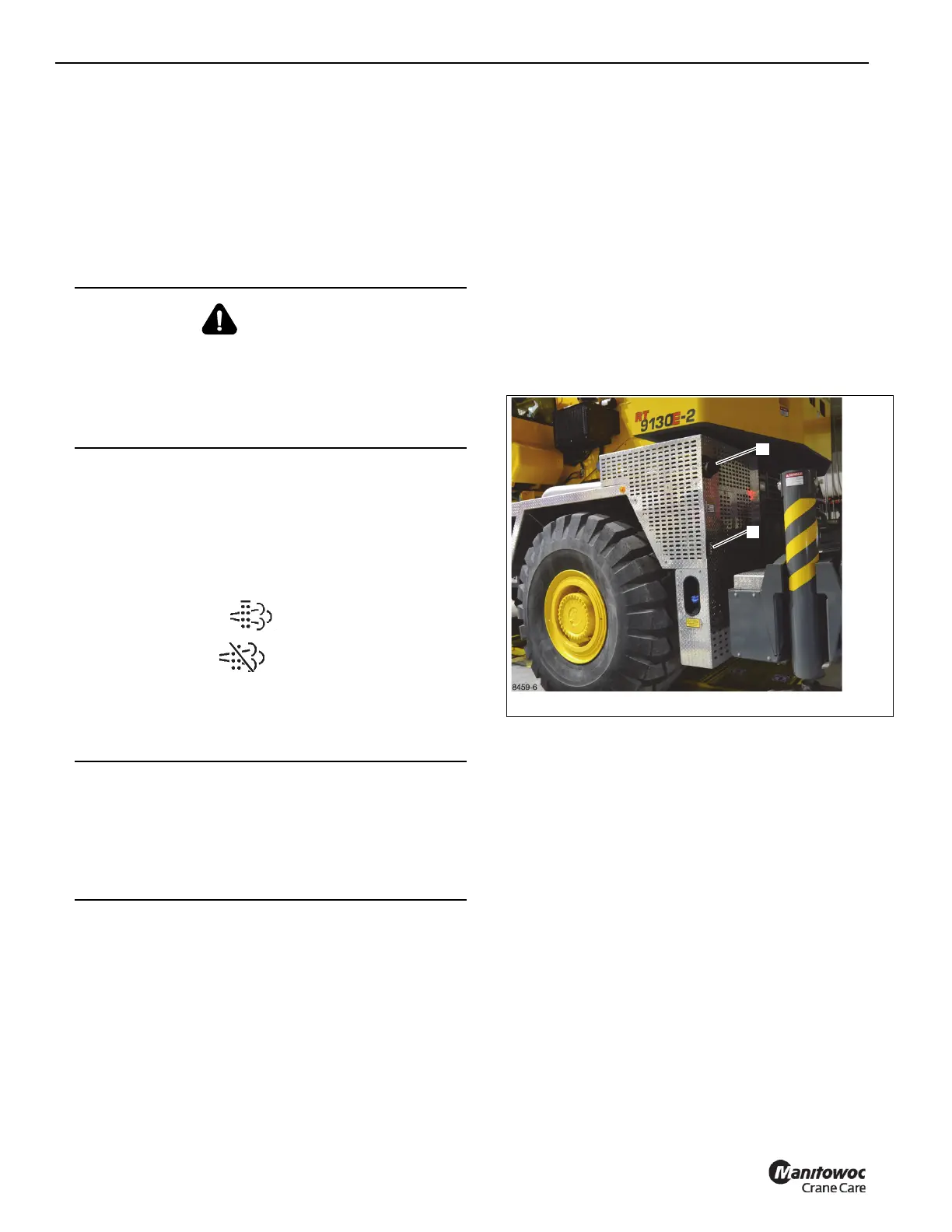
As a warning, the light (1, Figure 3-6) below the exhaust pipe
(2, Figure 3-6) will blink during cleaning.
Pressing the brake or throttle pedal during cleaning or
activating the Inhibit Cleaning Switch will interrupt the
manual cleaning process.
Make sure the crane and surrounding area are monitored
during manual cleaning. If any unsafe condition occurs, shut
off the engine immediately.
During this period the sound of the engine may change.
When manual cleaning is complete the engine will return to
it’s normal idle speed.
Boom Tele-1 / Tele-2 Select Switch &
Indicator
The Tele-1 / Tele-2 boom section select switch (10,
Figure 3-5) and indicator (11) are located on the overhead
control panel. This switch is a three position rocker switch
that is used in conjunction with the Boom Auto/Manual
Telescope Mode Switch (12, Figure 3-5).
When the boom mode switch (12) is positioned to manual,
the boom telescope section select switch is positioned to
either of the two positions. When placed in the upper
position, the Tele-2 can be extended. When the Tele-2 is fully
extended, the Tele-3 and Tele-4 can be controlled.
The Tele-1 / Tele-2 indicator (11) will illuminate when the
switch is positioned in either Tele-1 or Tele-2 position.
Boom Manual/Auto Switch
The Boom Manual/Auto Telescope Mode Switch (12,
Figure 3-5) and indicator (13) are located on the overhead
control panel. The switch is a two-position rocker switch,
Auto or Manual. This switch has a lock to prevent accidental
activation.
WARNING
Fire or Burn Hazard!
During the cleaning process the exhaust becomes very
hot. Do not park the vehicle near flammable objects.
Use caution near the exhaust tailpipe during cleaning as it
will become very hot.
CAUTION
Avoid Crane Damage!
Do not engage the parking brake while the vehicle is
moving. Damage to the crane can occur.
Disengage the parking brake before driving. Damage to
the crane can occur.