Grove Published 3-1-2018, Control # 559-03 3-5
RT9130E-2 OPERATOR MANUAL OPERATING CONTROLS AND PROCEDURES
Axle Oscillation Lockouts Operation . . . . . . . . . 3-38
General Crane Operation . . . . . . . . . . . . . . . . . . . 3-38
Pump Drive . . . . . . . . . . . . . . . . . . . . . . . . . . . . . 3-38
Control Lever Operation . . . . . . . . . . . . . . . . . . . 3-39
Preload Check . . . . . . . . . . . . . . . . . . . . . . . . . . 3-39
Using Your Load Chart . . . . . . . . . . . . . . . . . . . . 3-39
Proper Leveling of the Crane . . . . . . . . . . . . . . . 3-40
Setting the Outriggers . . . . . . . . . . . . . . . . . . . . . 3-40
Outrigger Monitoring System (OMS) (Optional) . 3-41
Engaging the Mid-Extend Lock Pin. . . . . . . . . . . 3-42
Stowing the Outriggers . . . . . . . . . . . . . . . . . . . . 3-42
Stowing the Mid-Extend Lock Pin . . . . . . . . . . . . 3-42
Swinging the Boom . . . . . . . . . . . . . . . . . . . . . . . 3-42
Elevating and Lowering the Boom . . . . . . . . . . . . 3-43
Telescoping the Boom . . . . . . . . . . . . . . . . . . . . . 3-43
Lowering and Raising the Hoist Cable. . . . . . . . . 3-44
Raising and Lowering the Hydraulic Jib. . . . . . . . 3-44
Operational Aids . . . . . . . . . . . . . . . . . . . . . . . . . . 3-45
Rated Capacity Limiter (RCL) System. . . . . . . . . 3-45
Control Lever Lockout System. . . . . . . . . . . . . . . 3-46
Stowing and Parking . . . . . . . . . . . . . . . . . . . . . . . 3-46
Unattended Crane . . . . . . . . . . . . . . . . . . . . . . . . 3-47
CONTROLS AND INDICATORS
The engine is electronically controlled by the Electronic
Control Module (ECM); it is the control center of the entire
engine system. The ECM processes all of the inputs and
sends commands to the fuel systems as well as vehicle and
engine control devices. This Operator Manual does not
include information on the engine ECM, however a separate
manual as prepared in detail by the engine manufacturer is
shipped with the crane from the factory.
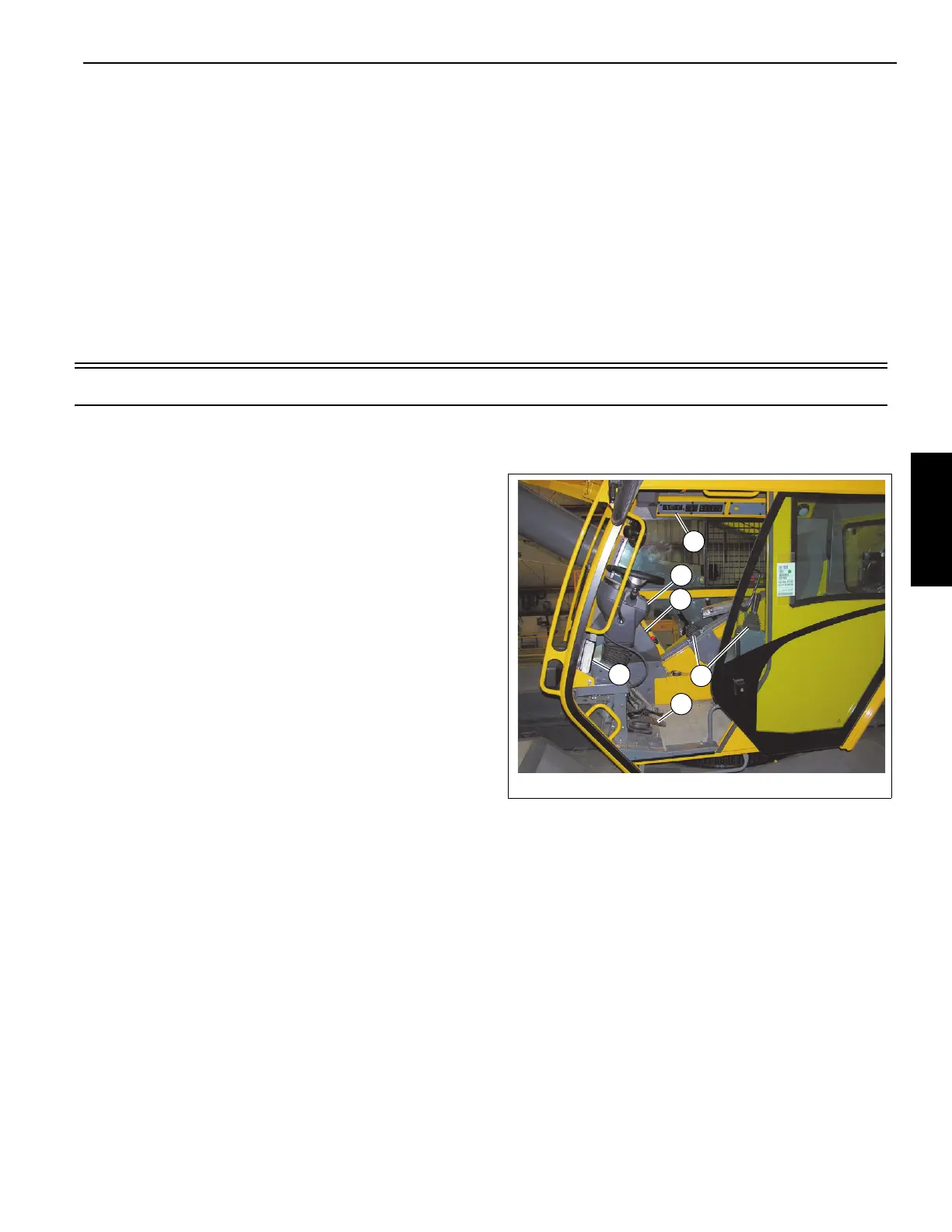
All the controls and indicators to operate and monitor crane
functions are found inside the crane cab (Figure 3-1) and
include the following:
1. Foot Pedals
2. Outrigger Controller
3. Seat Joystick and Armrest Controls
4. Side Display Panel
5. Steering Column
6. Overhead Control Panel
STEERING COLUMN
The steering column assembly in Figure 3-2 is a pedestal
style tilt and telescoping steering column. It has the ability to
tilt forward 30° or be raised vertically approximately 60 mm
(2.5 in). It also includes the ignition switch and the CAN bus
gauge display (11, Figure 3-2).