Grove Published 3-1-2018, Control # 559-03 3-19
RT9130E-2 OPERATOR MANUAL OPERATING CONTROLS AND PROCEDURES
collar are engaged with the splines on the differential case
and the axle shafts and the differential assembly are locked
together and there is no differential action between the
wheels. When positioned to Unlock, there is normal
differential action between the wheels all the time. The
amber indicator on the steering column is illuminated when
the proximity switches in each axle are activated.
CAB DOOR RELEASE
Use the Cab Door Release Lever (10, Figure 3-9) to open
and close the cab door from inside the cab.
SEAT BACK ADJUSTMENT
To adjust the back of the seat press the adjustment knob (11,
Figure 3-9) and then adjust the seat as needed.
A/C HEATER, CLIMATE CONTROL
The crane cab Air Conditioner/Heater Climate Control unit
(16, Figure 3-9) is located in the cab under the driver’s seat.
The vents (12) are part of the climate control unit and can be
adjusted to direct the flow of air.
SEAT SLIDE LEVER
Moving the Seat Slide Lever (13, Figure 3-9) will slide the
seat only, either forward or backward.
SEAT FRAME SLIDE LEVER
Moving the Seat Frame Slide Lever (14, Figure 3-9) will slide
the seat and the seat frame, with armrest controls, either
forward or backward.
ARMREST ADJUSTMENT
The Armrest and armrest controls can be adjusted using the
adjustment knobs (15, Figure 3-9). Loosen the knob and
rotate the entire armrest to the desired position, retighten the
knob when finished making the adjustment.
HOIST ROTATION INDICATORS (HRI)
The Hoist Rotation Indicators for the auxiliary and main hoist
is located on top of each hoist control lever (1,4, Figure 3-9).
Each indicator is electronically driven by an input signal from
a sensor attached to its related hoist and an output signal
from a control module. Each hoist control lever (1,4) pulses
when its hoist is running so the operator’s thumb can sense
it.
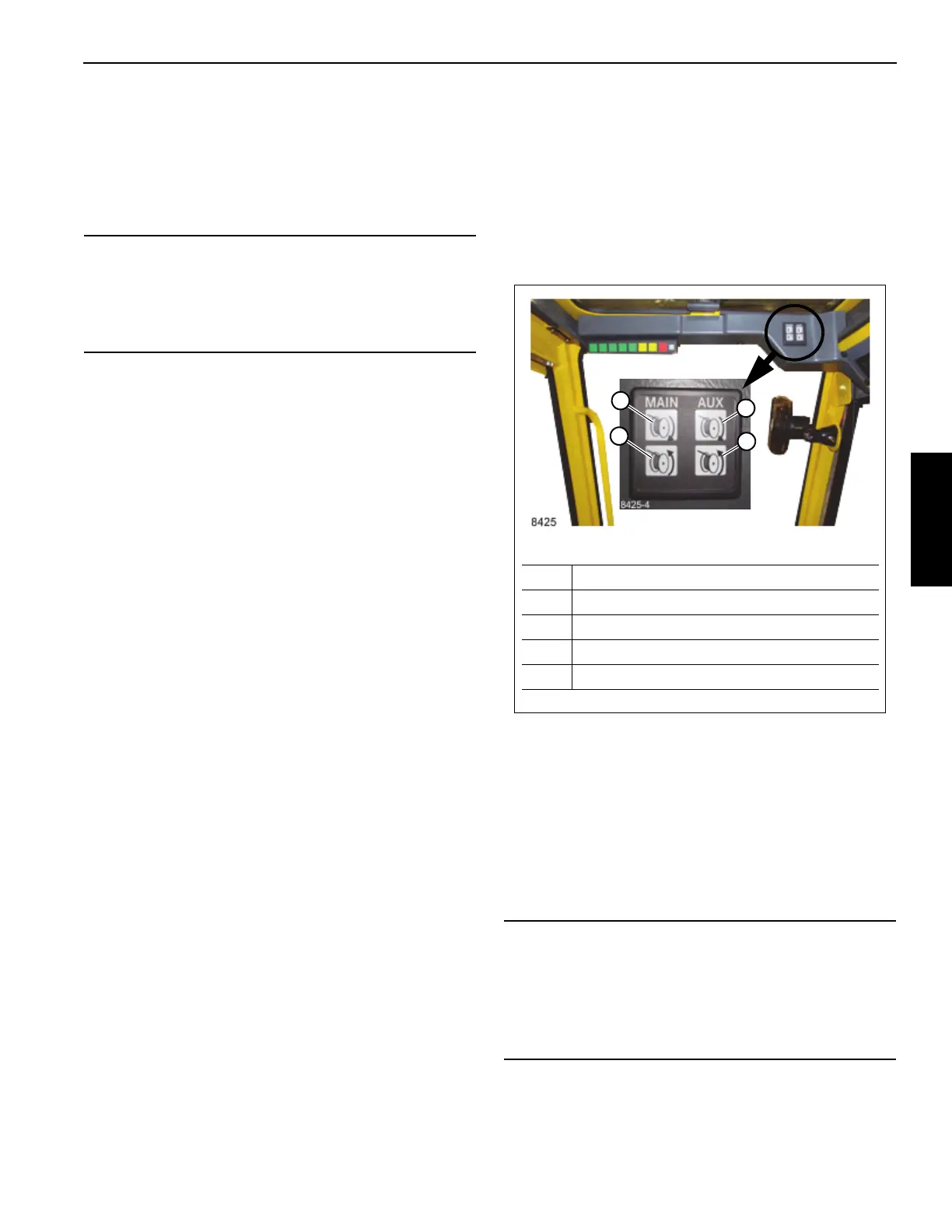
HRI Display
The display is located in the front overhead panel
Figure 3-10. The LED display illuminates to indicate the
current hoist in operation and which direction the hoist is
rotating.
CAB TILT SWITCH
The Cab Tilt Switch (17, Figure 3-9) is located in the right
arm rest. It is a three position, momentary spring centered to
off rocker switch. It has two positions, Up and Down, allowing
the cab to be tilted either up or down.
NOTE: The Parking Brake must be engaged to operate the
Cab Tilt feature and the cab must be completely
down for the drive functions to be enabled.
CAUTION
Axle Damage!
Operating the machine with the differentials in the locked
position while maneuvering on improved surfaces may
result in damage to the axles.
CAUTION
Avoid Crane Damage!
Do not engage the parking brake while the vehicle is
moving. Damage to the crane can occur.
Disengage the parking brake before driving. Damage to
the crane can occur.
FIGURE 3-10
8425
Item Description
1 Main Hoist UP (Clockwise)
2 Main Hoist DOWN (Counterclockwise)
3 Auxiliary Hoist UP (Clockwise)
4 Auxiliary Hoist DOWN (Counterclockwise)
1
2
3
4