4-25
RT9130E-2 OPERATOR MANUAL SET-UP AND INSTALLATION
Published 3-1-2018, Control # 559-03
9. At the rear stowage support bracket, insert the pins
(16a) and retaining clips stowed in the 7 m (23 ft) section
stowage lugs and into the connection between the 11 m
(36 ft) extension and 7 m (23 ft) section attaching fittings
(Detail C) (Figure 4-15).
10. At the fly section sheave end (Detail D) (Figure 4-15),
swivel the catch hook (32) to engage the latch securing
the base extension to fly section.
11. Ensure the attach pins and retaining clips attaching the
23 ft section to the guide rail bracket (Detail B)
(Figure 4-15) are in place.
12. Ensure pin (16b) and retaining clip attaching fly section
to boom base section rear support bracket (Detail C)
(Figure 4-15) are in place.
13. At the guide rail, pull downward on the eye bolt and fold
in the guide rail and release the eye bolt to lock the guide
rail in the stowed position (Detail B) (Figure 4-15).
14. Rig boom nose and hoist cable. Operate crane using
normal operating procedures.
CONNECTING AND DISCONNECTING
HYDRAULIC BOOM EXTENSION
Connecting
When working with just the main boom for longer periods of
time, the hydraulic connection between the hose drum and
the main boom should be disconnected. This prevents
unnecessary reeling and unreeling of the hose.
Establish a Hydraulic Connection Between the Boom
Extension and the Main Boom
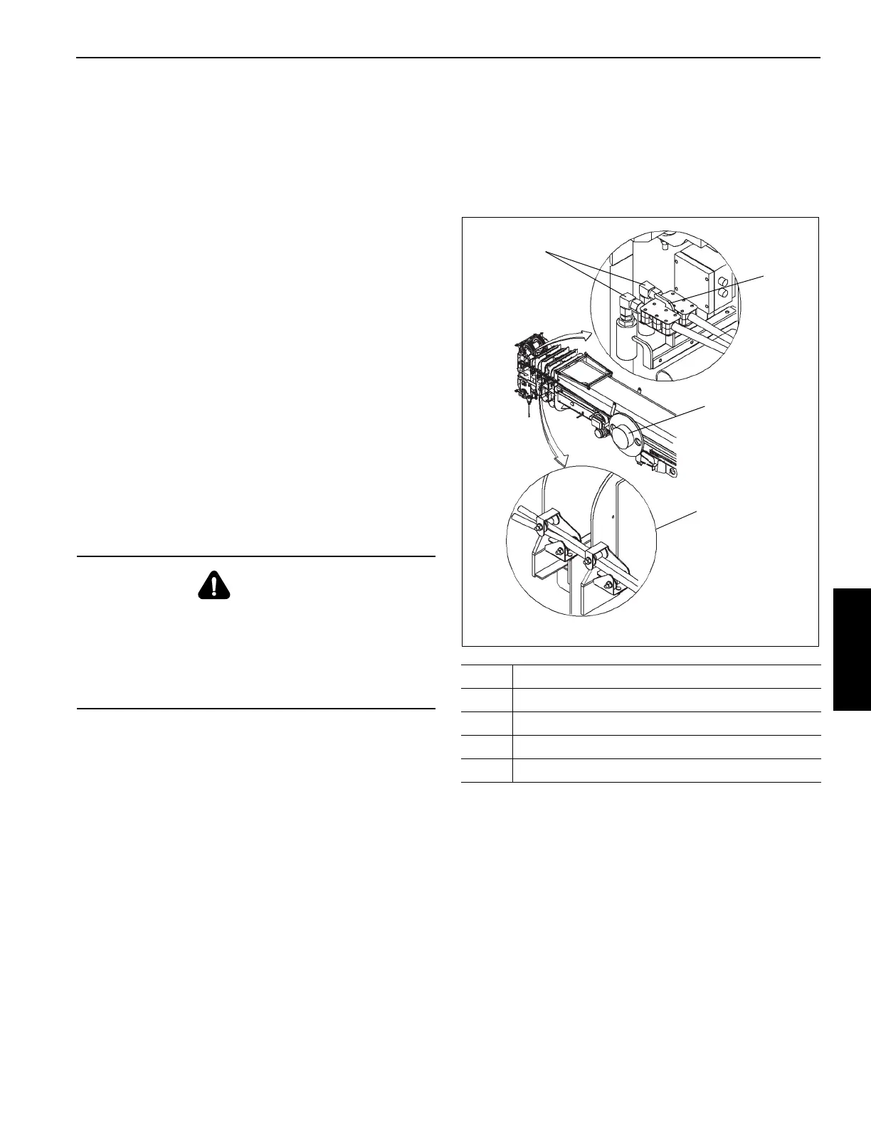
If the hoses are stowed on the holder on the boom base
section, release the hose drum (4) (Figure 4-16) lock pin and
pull the hydraulic hoses toward the boom nose. Anchor the
hydraulic couplings (1) at the holder (2) on the boom nose.
Guide the hydraulic hoses through the guide rollers (3).
1. Unwind the hoses on the lattice extension.
2. Remove the dust caps from the couplings on the lattice
extension and the drum hoses.
3. Connect the lattice extension hoses to the hose drum
hoses. Do not detach the drum hoses from the holder on
the boom nose.
Establish an Electrical Connection Between the
Lattice Extension and the Main Boom
1. Remove the bypass plug from the electrical junction box
on the boom nose.
2. Unwind the electrical cable from the jib.
3. Disconnect the cable from the dummy plug on the jib.
4. Connect the jib cable to the boom nose junction box.
DANGER
If hose couplings are detached from boom after hose
drum lock pin is released, do not release hose couplings
until they have been re-attached to the boom. If hose
couplings are released after being detached from the
boom, hoses will spring back uncontrollably due to the
spring force in the hose drum.
Item Description
1
Hydraulic Couplers
2 Holder
3 Guide Rollers
4 Hose Drum