ELECTRIC SYSTEM TMS700E SERVICE MANUAL
3-2 Published 01-29-2015, Control # 512-01
NOTE: Fuse 1 is energized when the batteries are
connected and the ignition switch is in the ignition
(RUN) and (START) positions.
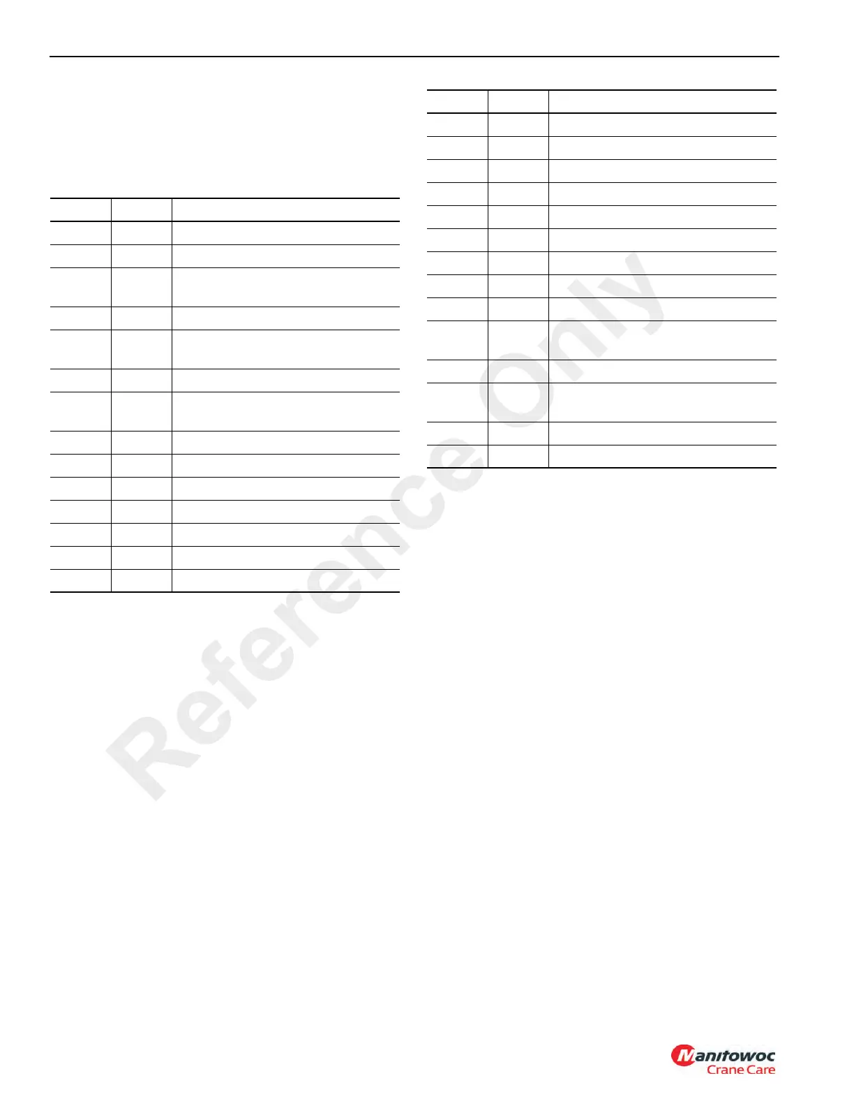
The following carrier fuse assignments (Table 3-1) apply:
Table 3-1
A 30 amp circuit breaker is installed inside the battery box
compartment. It protects the headlights, marker lights, and
gauge lights circuits.
Fuses 51, 52, 53, 54 and 55 are inside the battery box
compartment. These fuses protect the electrical power
system.
Fuse Amp Fuse Assignment
F1 5 ECM Ignition Signal
F2 10 Ignition
F3 20
Outrigger Solenoids, Daytime
Running Lights
F4 5 Gauge Lights
F5 10
Console Lamps, Gauges, Buzzer,
SW LEDS
F6 5 Horn
F7 10
Windshield Wiper/Washer
Beacon Light
F8 5 Cab Circulating Fan, Heater Valve
F9 10 Air Dryer
F10 5 Dome Light
F11 8 12 Volt Power Outlet (8 A Max)
F12 30 Hydraulic Oil Cooler Fan
F13 20 Turn Signals, 4 Ways
F14 15 Stop Lights
F15 7.5 Backup Lights and Alarm
F16 20 Fan Motor, A/C CLutch
F17 30 A/C Condensor Fans
F18 3 Spare (3 A Max)
F19 10 Carrier Marker and Clearance Lights
F20 10 Carrier Marker and Clearance Lights
F21 10 Left Head Light Lo Beam
F22 10 Right Head Light Lo Beam
F23 10 Right Head Light Hi Beam
F24 10
Left Head Light Hi Beam and Hi
Beam Ind
F25 5 S/S Ignition ON Relays
F26 5
ACC1, ACC2, Daytime Running
Lights Relay
F27 5 DEF Level Gauge
F28 5 Spare
Fuse Amp Fuse Assignment
Reference Only

 Loading...


