HYDRAULIC SYSTEM TMS700E SERVICE MANUAL
2-28 Published 01-29-2015, Control # 512-01
Procedure For Checking Front Steering
Relief Valve Pressure
1. Install pressure check diagnostic quick disconnect with
gauge on test nipple at the inlet of the power steering
gear box. (See Figure 2-17)
2. Disconnect hose from right front steer cylinder. Plug
hose. Plug or cap cylinder port also. (See Figure 2-18.)
3. Start engine and throttle up to full RPM. Attempt to turn
the steering wheel left or right.
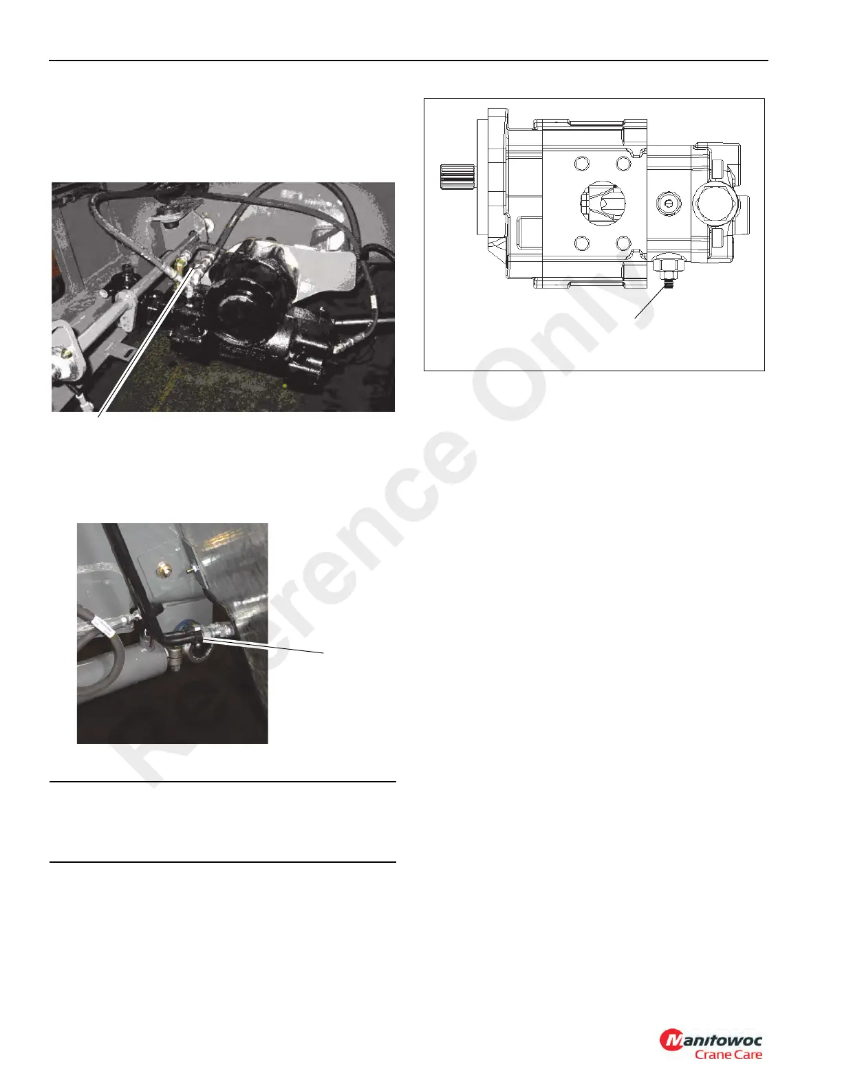
4. Adjust the priority flow relief valve (Figure 2-19) in the
pump in to increase or out to decrease to attain a
pressure of 150 ± 4 bar (2175
± 50 psi).
5. Stop engine. Remove quick disconnect and gauge.
Connect steer hose to right front steer cylinder.
DIRECTIONAL CONTROL VALVES
Description
The directional control valves direct and control hydraulic oil
flow from the pumps to the boom lift and telescope cylinders,
each hoist motor, the swing motor, the counterweight
removal/cab tilt cylinders and the front steer cylinders via the
steer control valve. The swing directional control valve and
the boom lift/telescope/hoist directional control valve are
located on the outside of the right superstructure side plate.
Each valve bank is removed and installed as an assembly.
The boom lift/telescope/hoist directional control valve
(Figure 2-21) is a sectional, hydraulic remote pilot actuated
three position four way, pressure compensated, closed
center directional valves. The inlet section contains a pump
unloading valve and load sense relief valve set at 275.80 bar
(4000 psi) protecting the main and auxiliary hoist and boom
lift sections. The unloading valve has a 20.69 bar (300 psi)
standby or pump margin pressure setting. The boom lift
retract has a thermal relief set at 255 bar (3700 psi). The
telescope section has port relief’s set at 206.90 bar (3500
psi) for retract and 186.21 bar (2700 psi) for extend. All
working sections have a two position two way solenoid RCL
lockout valve in each pilot end cap.
The swing valve (Figure 2-22) is a sectional, hydraulic
remote pilot actuated three position four way open center
directional control valve. The inlet section has a 151.69 bar
(2200 psi) relief valve. Both working sections have anti void
check valves to provide make-up oil to the swing motor for
motor over-run when the valve is centered.
The counterweight removal/cab tilt directional control valve
(Figure 2-23) is a sectional, hydraulic remote pilot actuated
three position four way, pressure compensated, closed
CAUTION
To prevent pump damage or failure due to heat buildup,
run the engine at full RPM in this configuration for a
maximum of 15 to 30 seconds.
FIGURE 2-18
Disconnect
hose from
tube. Plug
hose.
FIGURE 2-19
Priority Flow
Relief Valve
Reference Only

 Loading...


