Grove Published 01-29-2015, Control # 512-01 2-27
TMS700E SERVICE MANUAL HYDRAULIC SYSTEM
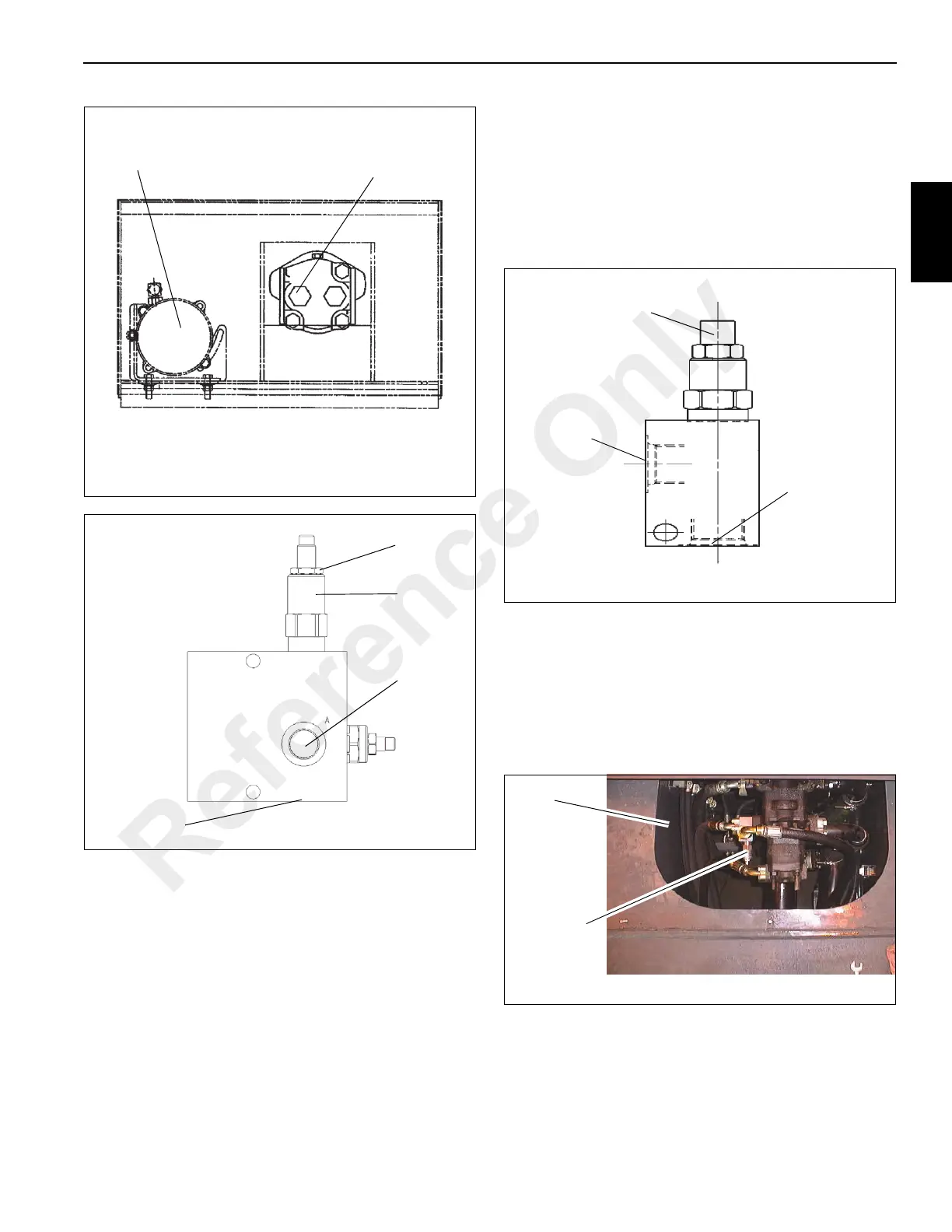
Procedure for Checking Center Front Jack
Cylinder (Fifth Jack) Relief Valve Pressure
1. Remove hose from Port 1 on the Center Front Jack
Cylinder Relief Valve. (See Figure 2-15.)
2. Install a tee fitting, reducer, and pressure gauge.
Reinstall hose onto tee fitting on Port 1.
3. With the engine running at idle RPM, fully extend the
center front jack cylinder (fifth jack).
4. While pressing the extend switch and the front jack
activate switch on the outrigger control box, check the
pressure and adjust the relief valve to 14 +4/-0 bar (200
+50/-0 PSI) (Figure 2-15).
5. Remove pressure gauge and adapters from Port 1 and
reinstall hose.
Procedure for Checking Pump Mounted
Relief Valve Pressure
This relief valve is factory set at 310 ± 4 bar (4500 ± 50 psi).
As long as the relief settings on both the outrigger and main
crane functions are achievable, there is NO need to check or
set it. If there is a problem with either relief setting, contact
Manitowoc Crane Care for assistance. (See Figure 2-16.)
Air Conditioning
Motor Port P
Compressor
6152-6
FIGURE 2-13
6787-1
FIGURE 2-14
Port GP
Air Conditioning Circuit Relief:
Remove cap, loosen jam nut and
turn stem in (CW) to increase or
out (CCW) to decrease pressure.
Port A
Jam Nut
Relief
Adjustment: Turn
clockwise to increase
pressure.
Port 1
Port 2
6143-2
FIGURE 2-15
FIGURE 2-16
Left Side
Engine
Compartment
Relief
Reference Only

 Loading...


