ELECTRIC SYSTEM TMS700E SERVICE MANUAL
3-12 Published 01-29-2015, Control # 512-01
3. Repair is straightforward.
a. For a gauge or meter, check or replace fuse,
remove gauge or meter, install new gauge or meter,
then test gauge or meter.
b. For a sender, check or replace fuse, remove sender,
install new sender, then test sender and gauge or
meter. See Instrument Replacement, page 3-17 in
this section for details on removing and installing
gauges and meters.
Troubleshooting Alarms, Indicators, and
Emergency Components
1. If an indicator won’t work when it is supposed to, check
its lamp first. Replace any damaged lamp. Then check
and replace fuse as applicable, especially if all other
components downstream from the fuse are not working.
Also, check and replace its relay as applicable.
2. If an alarm or an emergency component won’t work
when it is supposed to, check and replace its fuse,
especially when all other components downstream from
the fuse are not working. Also, check and replace its
relay as applicable.
3. Check the alarm or indicator or emergency component,
its sensing component, and circuit for continuity
problems and other problems. Repair any faulty alarm or
indicator or emergency component or sensing device
(switch, relay, sending unit). Repair wiring if faulty.
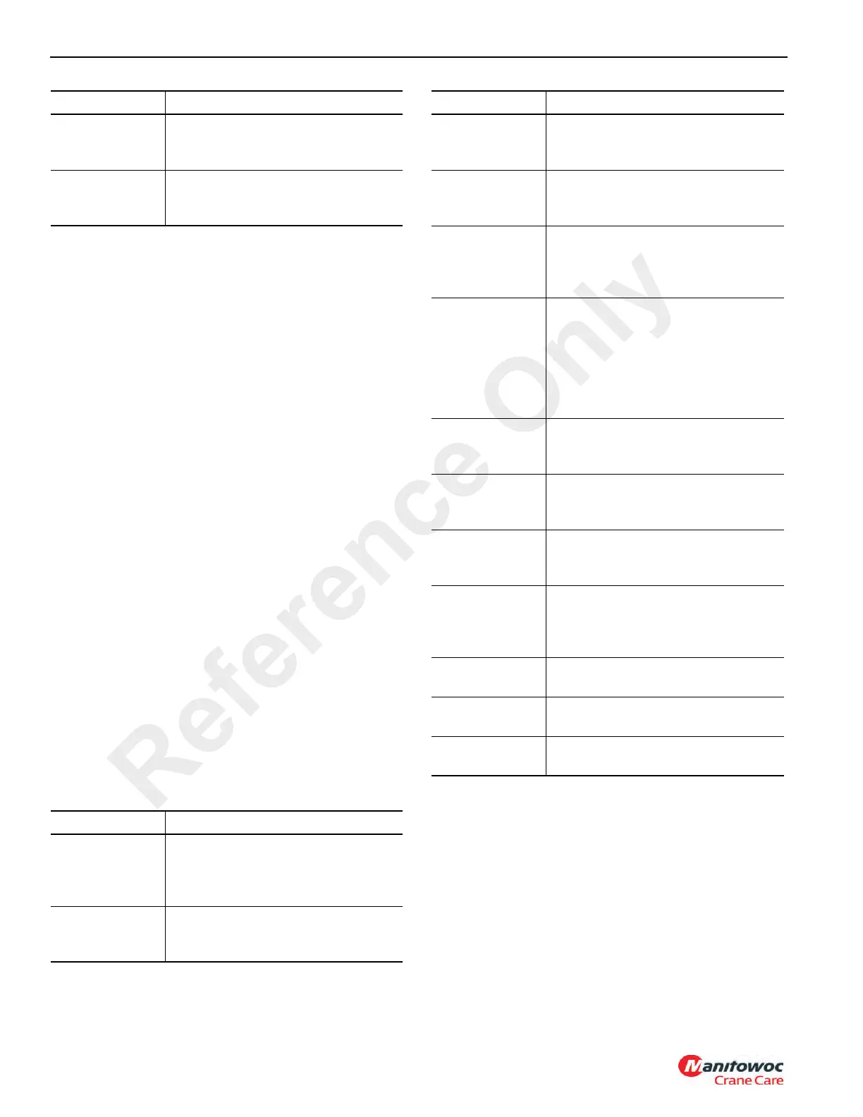
The following carrier circuit designs apply (Table 3-12)
(connecting wiring and passage through swivel slip ring -- as
applicable -- is understood):
Table 3-12
The following superstructure circuit designs apply (Table 3-
13) (connecting wiring and passage through swivel slip ring -
- as applicable -- is understood):
Tachometer
F5/F9, tachometer. Meter is
grounded. Branch from tachometer to
tachometer sender to ground
Speedometer
F5, gauge. Gauge is grounded.
Branch from speedometer to engine
ECM and back to speedometer
Component Circuit
Backup Light
and Backup
Alarm
F15, backup switch, relay K108, then
to backup light in parallel with backup
alarm; then from light and alarm to
grounds
Park Brake
Indicator
F5, indicator, normally closed park
brake pressure switch on cab front
console control valve, ground
Gauge/Meter Circuit
Steering Wheel
Horn
F6, horn relay K106 coil, horn switch,
ground. Parallel branch from horn
relay contacts, horn, ground
Low Air
Pressure
Indicator
F5, to indicator or buzzer to two
parallel normally closed pressure
switches on the dual brake valve
Tire Inflation On
Indicator
F5, to indicator or buzzer to the
normally open pressure switch on the
cab front console control valve to
ground.
Swing Brake On
Indicator
F5, to indicator or buzzer to the
normally open pressure switch on the
cab front console mounted trailer
brake control valve to normally open
pressure switch on the trailing boom
swing valve on the superstructure to
ground
Hydraulic Pump
Engaged
Indicator
F5 to indicator to switch on pump
disconnect lever to ground
Cross Axle
Differential Lock
On Indicator
F5 to indicator to switch on axle to
ground
Inter-Axle
Differential Lock
On Indicator
F5 to indicator to normally open
pressure switch on cab front console
control valve to ground
Suspension
Deflated
Indicator
F5 to indicator to four (one at each air
bag suspension) normally closed
pressure switches connected in
series to ground
Engine Stop
Indicator
F5 to indicator or buzzer to engine
ECM
Engine Warning
Indicator
F5 to indicator to engine ECM
Engine Service
Indicator
F5 to indicator to engine ECM
Component Circuit
Reference Only

 Loading...


