ELECTRIC SYSTEM TMS700E SERVICE MANUAL
3-4 Published 01-29-2015, Control # 512-01
Relays
The carrier has 22 relays (Table 3-2) which control many of
its functions. Relays K101 through K124 are located in the
cab circuit breaker and relay panel assembly. When any
relay coil is energized, its contacts either close or open. This
allows power to go to or be removed from the related circuits.
For any relay coil to energize, the battery must be
connected.
Table 3-2
The coil of the accessory relays (K101 and K102) are
energized when the ignition switch is at the RUN (1) or ACC
(3) position.
The coil of the hydraulic oil cooler relay (K103) is energized
when the hydraulic oil temperature switch closes.
The coil of the outrigger enable relay (K105) is energized
when the park brake on indicator pressure switch contacts
are closed.
The coil of horn relay (K106) is energized when the horn
button is depressed.
The coil of the air dryer heater relay (K107) is energized
when the contacts of accessory relay (K101) are closed.
The coil of back up relay (K108) is energized when the
contacts of accessory relay (K102) and back up switch are
closed.
The coils of turn signal relays (K109 thru K112) are
energized and de-energized by the turn signal flasher.
Superstructure Relay Panel and Fuse Panel
NOTE: Refer to Figure 3-3 for electrical connections
Most superstructure electrical circuits are protected by the
components of the relay panel assembly (Figure 3-4) and the
fuse panel (see Figure 3-2).
The relay panel assembly contains 6 relays. It is located on
the outside rear wall of the superstructure cab. Access is
gained by removing the cover that covers the rear outside of
the cab.
Fuses
The fuse panel is located on the rear wall of the cab behind
the seat and contains 20 fuses. To gain access to the fuses,
loosen the thumb screws and remove the cover. A decal
(Figure 3-4) in the cover identifies each fuse, its function and
its amperage. Fuses 1, 2, 3, 4, 5, and 6 are energized when
the battery is connected. Fuse 7 thru 16 are energized when
the battery is connected and the ignition switch is in the RUN
(1) or ACC (3) position.
The following superstructure fuse assignments (Table 3-3)
apply:
Table 3-3
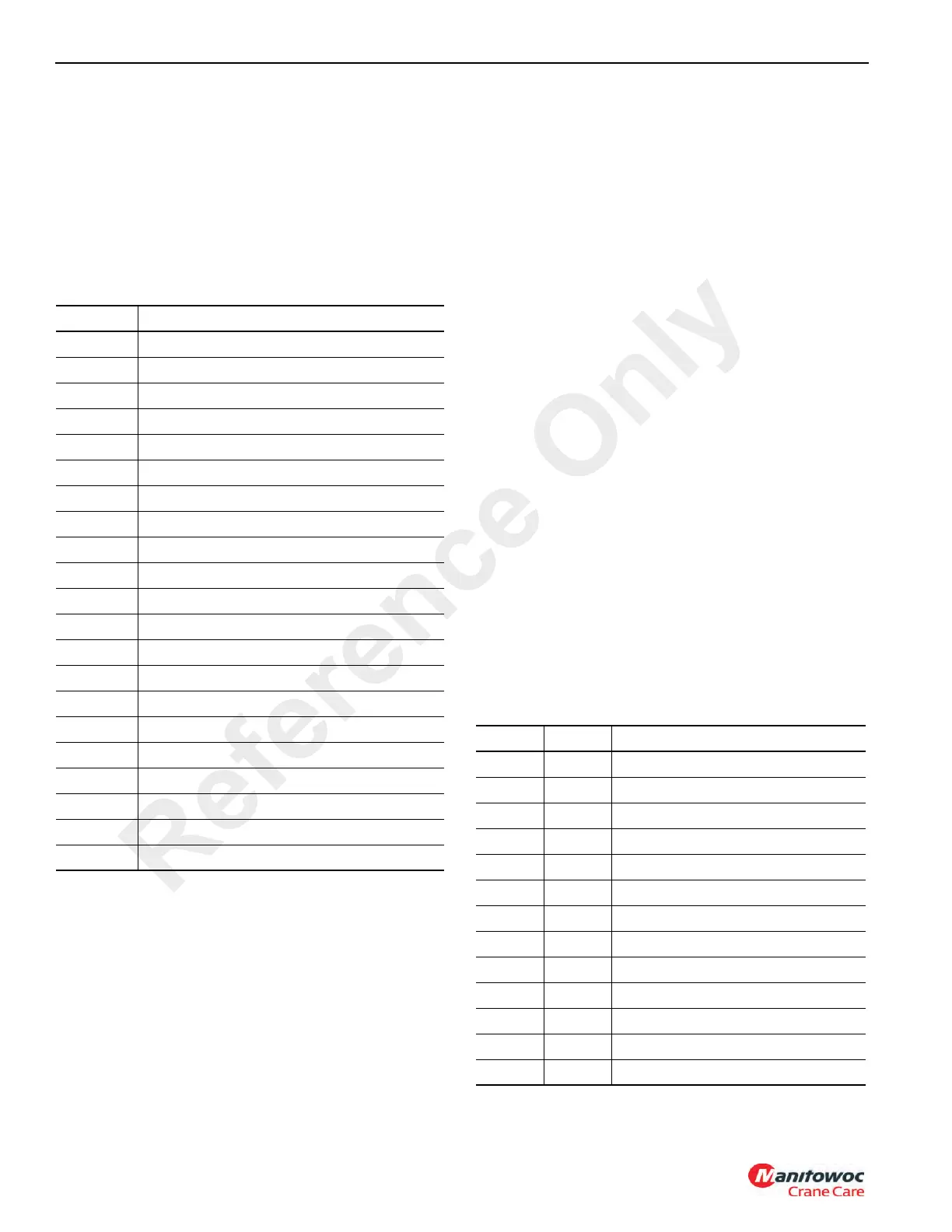
Relay Relay Assignment
K101 #1 ACC
K102 #2 ACC
K103 Hydraulic Oil Cooler
K105 Outrigger Enable
K106 Horn
K107 Air Dryer
K108 Backup Alarm and Lights
K109 Right Front Turn Signal
K110 Left Front Turn Signal
K111 Right Rear Stop/Turn Light
K112 Left Rear Stop/Turn Signal
K113 Hydraulic Boost
K114 A/C Condenser Fans
K115 Daytime Running Lights
K116 Remote Accelerator
K117 Fan Clutch
K118 Hydraulic Pump Engage Enable
K119 Hydraulic Pump Engage Lamp
K120 Anti-Restart
K123 S/S Inc./Dec., Regen Switches
K124 Hyd Oil Cooler Power
Fuse Amp Fuse Assignment
F1 10 Boom Flood Lights
F2 10 Cab Work Lights
F3 10 12V Dash Outlet (8A Max)
F4 5 Horn
F5 10 Radio (Opt), B+ Spare (8A Max)
F6 10 Dome LT, Gauge LTS
F7 10 Ignition
F8 5 Acc. Relay Coils
F9 10 Gauges, Warning Lights
F10 5 Swing Brake
F11 15 RCL/Unlock Solenoids
F12 10 Main Hoist Down, Aux Hoist Down
F13 5 Skywiper, Cab Fan
Reference Only

 Loading...


