POWER TRAIN TMS700E SERVICE MANUAL
7-40 Published 01-29-2015, Control # 512-01
GEARSHIFT AND TRANSMISSION SHIFT
AIR SYSTEM
Description
The remote location of the transmission from the shift lever in
the carrier cab requires a mechanical linkage between the
cab and transmission case. A master control unit is attached
to the bottom of the gearshift lever under the cab floor and is
mechanically connected by a universally jointed rod to a
slave shifter unit on top of the transmission case. All of the
motions of the gearshift lever are in this way transmitted to
the shift fingers that engage the shift bars and locks of the
transmission case. Range shifts for the transmission are
controlled by air operated master and slave valves.
The shift air system controls the selection of the transmission
ranges and is comprised of an air valve, air regulator, air
filter, range control valve, a range shift cylinder, and the
necessary connecting piping.
The range control valve is located on the shift lever in the
carrier cab, and the other valves and cylinders are mounted
on the transmission.
Refer to the Operator Manual for operation instructions.
Theory of Operation
The range control valve has two positions: HIGH (switch up)
and LOW (switch down). There are two air lines connected
between it and the air valve. One of these is the supply line
from the regulator, while the other is the air return to the air
valve.
When the range control valve is in the LOW position, air is
exiting the range control valve and enters the slave air valve
where it shifts the piston. This allows the air from the
regulator to exit the bottom port of the air valve, enter the low
range air port of the auxiliary shift cylinder, and shift the low
speed gear.
When the range control valve is in the HIGH position, air is
prevented from exiting the range control valve. This allows
the air entering the slave air valve from the regulator to move
the piston, routing the air out of the valve to the high range
port of the auxiliary shift cylinder. This moves the shift bar
shifting the high speed gear.
In addition to the range control switch, a LO-LO (deep
reduction) switch allows the operator to select two extra low
gears. This switch has a forward (IN) position for being in
deep reduction, and a rearward (OUT) position for being out
of deep reduction.
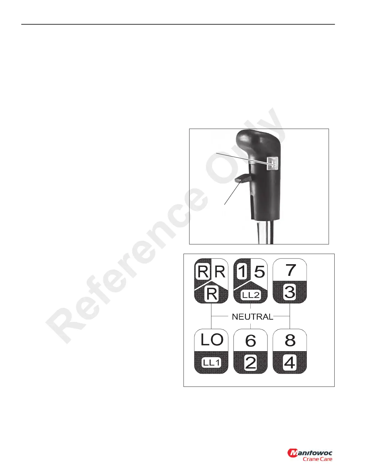
Shifting Gears
The manual transmission’s gear shift has six drive locations
and the neutral locations. The gear shift has a finger switch
(range control switch) for high range and low range, and a
thumb switch (deep reduction switch) for deep reduction
(Figure 7-27). These switches route air under pressure to
shift in high, low, or deep reduction ranges.
To change gears, the operator has to step on the clutch
pedal, use the finger or thumb switch to pick proper range,
use the gear shift to pick the chosen speed and direction,
and then step off of the clutch pedal (Figure 7-28).
FIGURE 7-27
Range
Control
Switch
Deep Reduction
Switch
6992-2
Reference Only

 Loading...


