Grove Published 01-29-2015, Control # 512-01 2-49
TMS700E SERVICE MANUAL HYDRAULIC SYSTEM
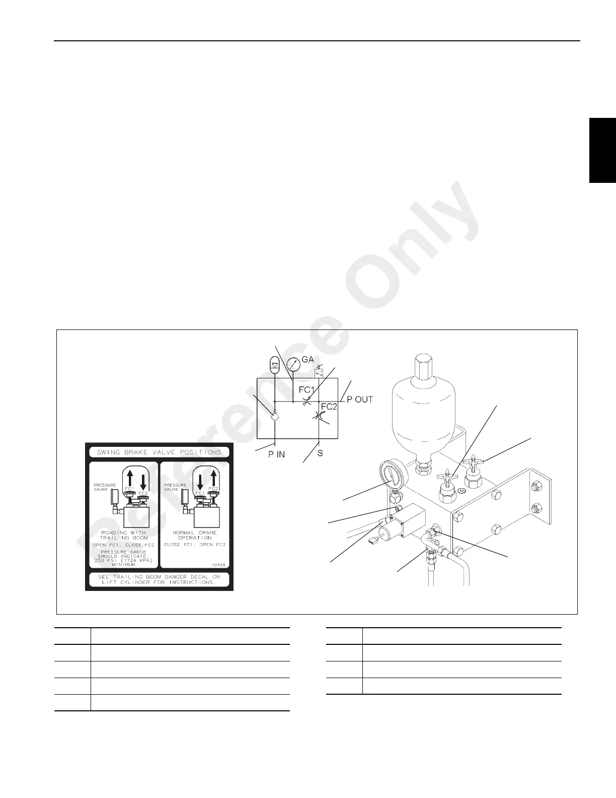
SWING BRAKE RELEASE VALVE
(OPTIONAL)
Description
The swing brake release valve (Figure 2-36) is used when
the crane is equipped with the trailing boom option. It is
located on the right side of the turntable, near the front. The
valve is used to keep the swing brake released when the
boom is in the trailing mode which is necessary to allow the
boom to swing for roading. This is done in the valve internally
by routing oil from the accumulator to the brake release port
keeping the brake released.
Incorporated within the valve is a check valve, two manually
operated valve cartridges, an accumulator, a pressure
gauge, and a pressure switch.
The two manually operated valves (FC1 and FC2) are used
to route pressure to the swing brake release port for either
craning or trailing boom operation. In the trailing boom mode,
FC1 is open and FC2 is closed. In the craning mode, FC1 is
closed and FC2 is open.
Maintenance
Removal
1. Tag and disconnect the hydraulic lines from the swing
brake release valve. Cap or plug all openings.
2. Tag and disconnect the electrical connector from the
pressure switch.
3. Remove the bolts, lockwashers, and washers securing
the valve in place and remove the valve.
Installation
1. Position valve on the turntable and secure with the bolts,
lockwashers, and washers.
2. Connect the electrical connector to the pressure switch.
3. Connect the hydraulic lines to the valve as tagged during
Removal.
6144-2
6144
FIGURE 2-36
6144-1
7
2
4
7
6
5
3
4
1
1
2
5
7
3
6
Item Description
1 Needle Valve FC1
2 Needle Valve FC2
3 Port P - To Swing Brake Release
4 Port S - From Swing Brake Manifold
Item Description
5 Port P - Pressure In
6 Check Valve - CK 1
7 Pressure Gauge
Reference Only

 Loading...


