Grove Published 01-29-2015, Control # 512-01 8-31
TMS700E SERVICE MANUAL UNDERCARRIAGE
chamber. Secure with outer shim washer(s) and snap
ring.
4. Rotate the adjusting shaft hex nut clockwise until the
slack adjuster arm and actuator rod holes line up with
the clevis holes.
5. Install the clevis pins and the cotter pins.
6. Adjust the brakes by turning the adjusting shaft hex
clockwise until the lining contacts the drum. Then rotate
the adjusting shaft hex counterclockwise 1/2 turn.
Adjustment Procedures
Brake Applied Stroke Measurement
Ensure that the brake applied stroke is within required values
as outlined below.
1. Chock the wheels.
2. Charge air tanks. Refer to Air System, page 8-47.
3. Release the parking brakes and shut down the engine.
4. Adjust the primary and secondary air tank pressures to
6.21 to 6.89 bar (90 to 100 psi). Refer to Air System,
page 8-47.
5. With service brakes released, measure distance from
slack adjuster clevis pin to chamber mounting face on
each brake. Refer to Dimension “A” in (Figure 8-25).
6. Starting with 6.21 to 6.89 bar (90 to 100 psi) air tank
pressure in both primary and secondary systems, fully
apply service brakes and hold brakes on. Do not pump
the brakes. Measure between the same points as in step
5 on each brake. This is Dimension “B” in (Figure 8-25).
7. Subtract Dimension “A” from Dimension “B” for each
brake position (Figure 8-25). This value cannot exceed
5 cm (2 in) on the front brakes or 6.3 cm (2.5 in) on the
rear brakes.
8. If any brake exceeds values shown in step 7, the brake
must be re-adjusted per the Brake Free Play
Measurement and Adjustment procedure that follows in
this section.
9. If after adjustment the requirements in step 7 cannot be
met, contact your distributor or Manitowoc Crane Care.
The crane cannot be driven on public roads until
repaired.
Brake Free Play Measurement and
Adjustment
The following procedure is required to ensure that the free
play of the brakes is within required values.
NOTE: If the brake is equipped with a spring type parking
chamber the spring must be caged before taking
measurements.
1. Chock the wheels and release the parking brakes.
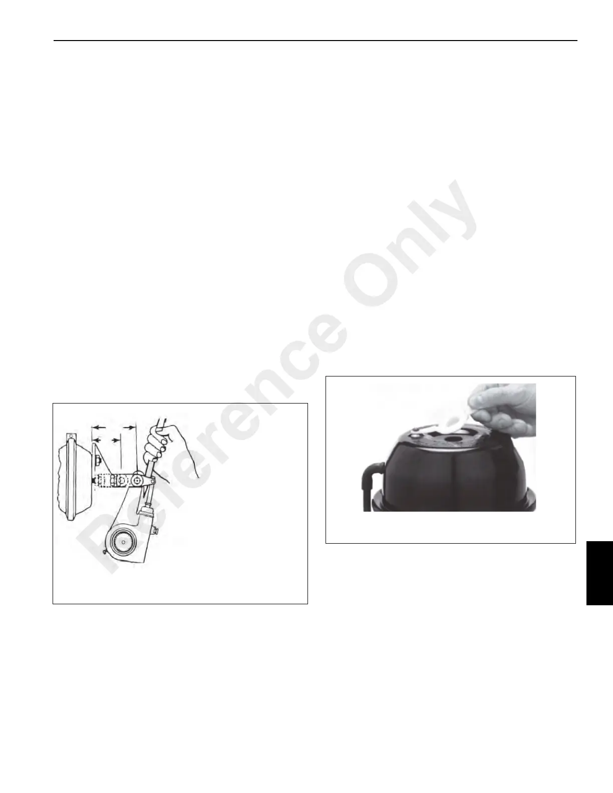
2. Remove the plastic end cap from the spring brake
chamber (Figure 8-26).
NOTE: If the items referred to in step 3 and 4 are not
stored on the chamber, they must be obtained from
the vehicle tool box or Manitowoc Crane Care, as
the piggyback spring brake cannot be manually
released without them.
3. Using a 3/4 inch wrench, unscrew the release-nut and
remove the nut, flatwasher and release-bolt from their
storage pocket on side of chamber (Figure 8-27).
FREE STROKE = B MINUS A
Drum brake free stroke must be
12.7 - 15.9 mm (0.5 - 0.625 in)
Disc brake free stroke must be
19.1 - 22.2 mm (0.75 - 0.875 in)
7094-2
A
B
MEASURE FREE STROKE
FIGURE 8-25
Reference Only
 Loading...


