HOIST AND COUNTERWEIGHT TMS700E SERVICE MANUAL
5-12 Published 01-29-2015, Control # 512-01
1. Measure the sensor input voltage from +10V terminal 1
to ground terminal 3 on the DTM3S connector. Measure
the pulsating return signal from +5V terminal 2 to ground
terminal 3 on the DTM3S connector. If the +10V is
applied to the sensor input and the +5V pulsating signal
is applied to the DTM3S connector terminal 2 and the
red LED still does not pulsate, the CPU is worn or
damaged and should be replaced.
2. If the +5V signal on terminal 2 does not oscillate, the
sensor is worn or damaged or the sensor adjustment air
gap from the drum is too wide. Adjust the sensor position
and retest. If oscillation does not occur, replace the
sensor.
Amber LED
With the green LED on continuously, and the red LED
pulsating (hoist is rotating), the amber LED should also be
pulsating. If the amber LED does not pulse on and off, a worn
or damaged CPU could be the problem. If the amber LED
pulsates, but the thumb thumper solenoid does not, then the
thumper solenoid is worn or damaged and should be
replaced or there are broken or pinched wires in the system.
The following should be used only after using the diagnostic
LEDs.
1. Using a digital voltmeter, check to see if the CPU is
receiving 12 volts between terminals A (red wire) and B
(black wire) of connector DT3S. If no voltage is present,
check wiring and circuit breaker or fuse.
2. Using a digital ohmmeter, check to see if the thumper
solenoid resistance is 12 ± 2 ohm. If the resistance does
not measure correctly the solenoid is worn or damaged
and should be replaced.
3. Using a digital voltmeter, measure the voltage on
thumper solenoid white feed wire 27. The voltage should
measure 12V. If voltage is not within ± 10 percent, check
the voltage at the fuse or circuit breaker. If the voltage
does not measure within ± 10 percent, trace the high or
low voltage back to the source and repair the defect. If
the voltage does measure within ± 10 percent, the
thumper solenoid white feed wire 27 is pinched; replace
it.
4. After disconnecting both ends of wire 508 (main hoist) or
509 (auxiliary hoist) between the thumper solenoid and
the CPU, measure the resistance of wire 508 or 509. If
the resistance measures more than 0.5 ohm, the wire is
worn or damaged; replace it.
Hoist Rotation Indicator (HRI) Display
System
The HRI Display consists of an LED display that indicates
the direction the hoist(s) are rotating, pressure switches that
monitor hydraulic pilot pressure, and a control module
mounted in the cab.
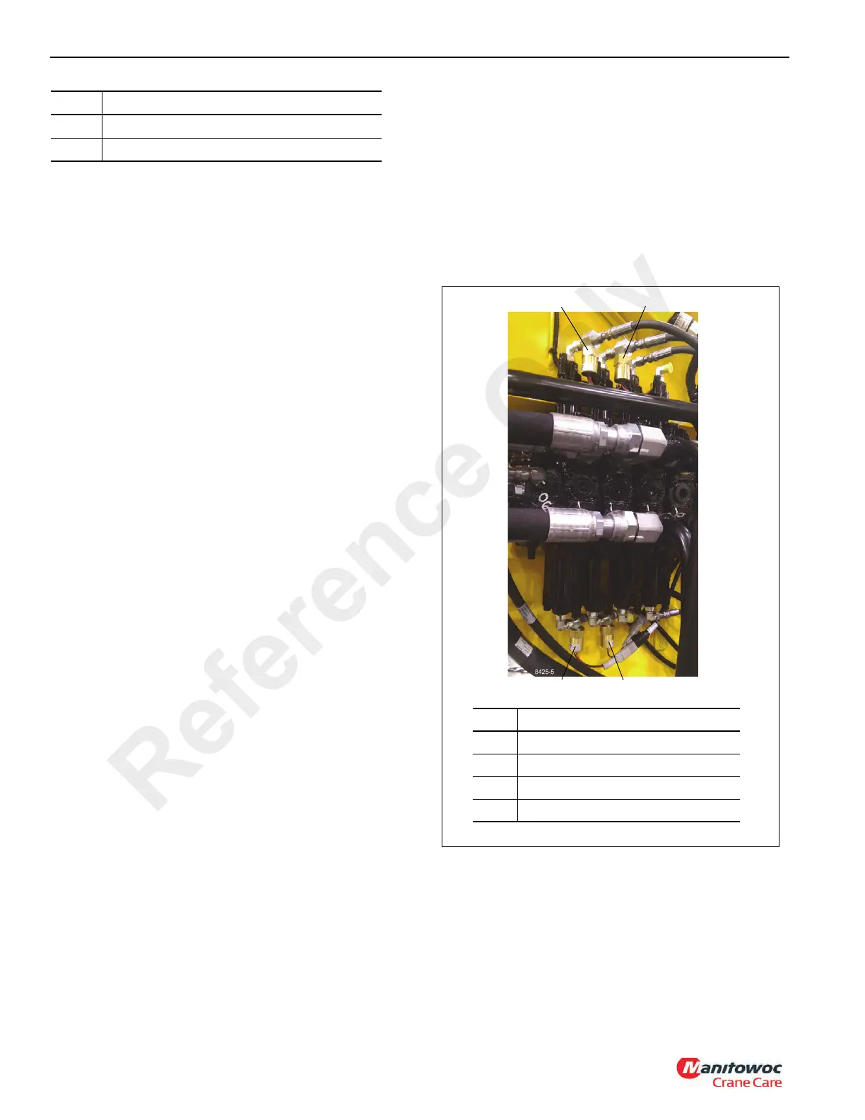
Pressure Switches
The pressure switches are located on the main control valve
Figure 5-6. The switch contacts close at 75 psi (5.17 bar).
HRI Display
The display is located in the front overhead panel Figure 5-7.
To replace the display, remove the overhead panel.
Disconnect the electrical connector and pry the display off of
the panel. Clean the panel where the display was affixed with
isopropyl alcohol, remove the paper from the adhesive back
of the new display and stick it into the panel. Connect the
12 Button
13 Thumb Thumper Rotation Indicator Solenoid
Item Description
FIGURE 5-6
8425-5
Item Description
1 Main Hoist Down Switch
2 Auxiliary Hoist Down Switch
3 Auxiliary Hoist Up Switch
4 Main Hoist Up Switch
1
2
4
3
TYPICAL
VIEW ONLY
Reference Only

 Loading...


