Grove Published 01-29-2015, Control # 512-01 5-11
TMS700E SERVICE MANUAL HOIST AND COUNTERWEIGHT
off, then either the CPU is damaged or the sensor is
damaged. The following should be used only after using the
diagnostic LEDs.
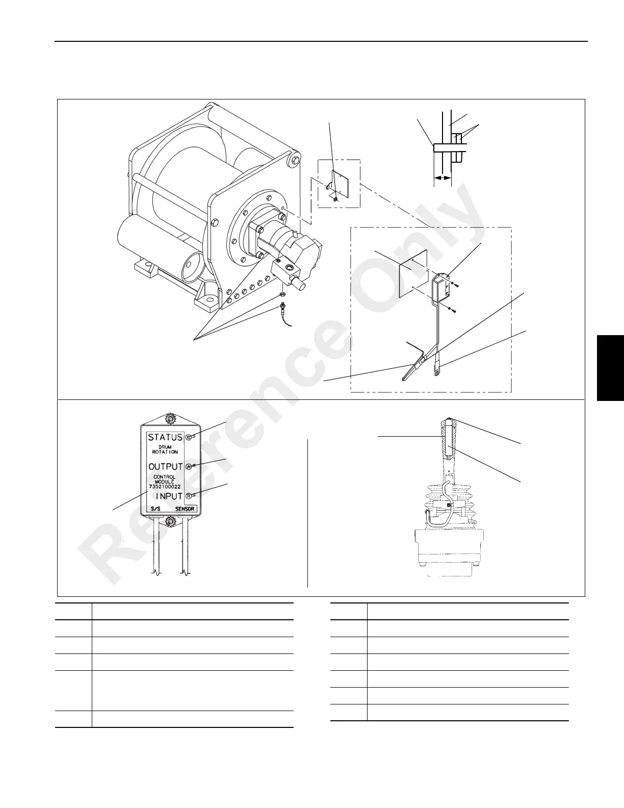
SINGLE AXIS CONTROLLER
CONTROL MODULE - CPU
FIGURE 5-5
1
4
3
2
11
8
9
10
1
13
12
5
6
7
Support End Bracket
31 mm (1.21 in.)
Lock Nuts
Sensing End
To Sensor
Connects to DT3S
Item Description
1 Control Module - CPU
2 Bracket
3 CPU Bolt (not shown) and Washer
4
Sensor (horizontal under brake clutch,
through support end bracket, shown with
lock nuts)
5DTM3S
6DTM3P
7DT3P
8 Green LED
9 Amber LED
10 Red LED
11 Lever Handle
Item Description
Reference Only
 Loading...


