HYDRAULIC SYSTEM TMS700E SERVICE MANUAL
2-46 Published 01-29-2015, Control # 512-01
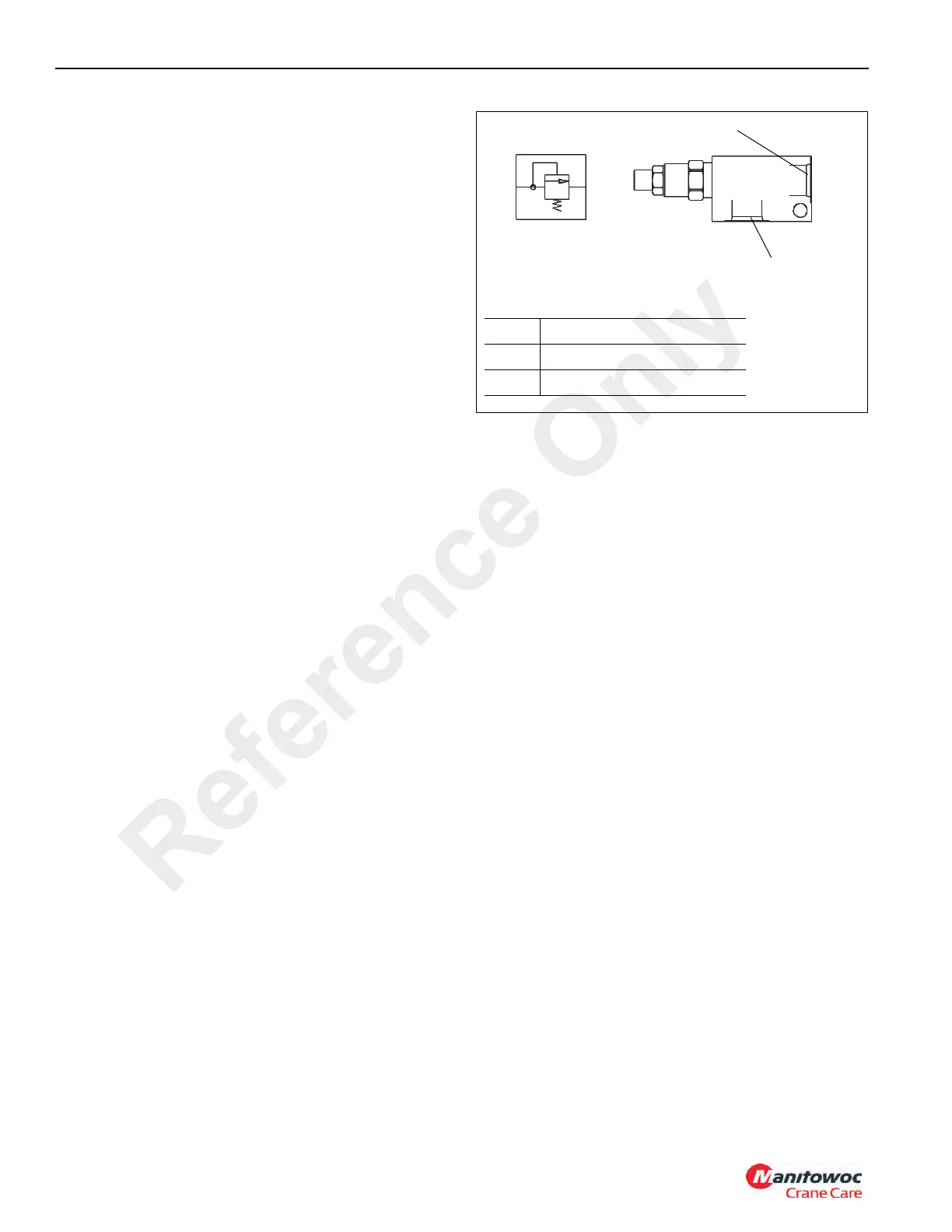
FRONT CENTER JACK RELIEF VALVE
Description
The pilot operated relief valve (Figure 2-33) is installed on
the right inside frame of the front outrigger box under the
right bottom side rail. Its purpose is to limit the piston
pressure of the front center jack not allowing it to raise the
crane.
The valve consists of a manifold and cartridge. When
pressure at the inlet port exceeds the bias spring force or
setting holding the valve closed, the valve will open directing
pressurized oil to the reservoir.
Maintenance
Removal
1. Tag and disconnect the hydraulic lines from the valve
and cap or plug all openings.
2. Remove the bolts, nuts and washers and remove valve.
Installation
1. Install the valve and secure with the washers, nuts and
bolts.
2. Connect the hydraulic lines as tagged during removal.
3. Check the valve and hydraulic connections for leaks.
Make repairs as needed.
PUMP MOUNTED RELIEF VALVE
Description
The in-line plumbed direct acting relief valve (Figure 2-34) is
installed onto the second section of pump #1. Its purpose is
to protect the pump section from over pressurization.
The valve consists of a manifold and cartridge. When
pressure at the inlet port exceeds the bias spring force or
setting holding the valve closed, the valve will open directing
pressurized oil to the reservoir.
Maintenance
Removal
1. Tag and disconnect the hydraulic lines from the valve
and cap or plug all openings and remove valve.
Installation
1. Connect the hydraulic lines as tagged during removal.
2. Check the valve and hydraulic connections for leaks.
Make repairs as needed.
1
6143
FIGURE 2-33
2
Item Description
1 Port 1 - Pressure Inlet
2 Port 2 - To Reservoir
Reference Only

 Loading...


