HYDRAULIC SYSTEM TMS700E SERVICE MANUAL
2-70 Published 01-29-2015, Control # 512-01
Assembly
NOTE: Lubricate seals and rings with clean hydraulic oil.
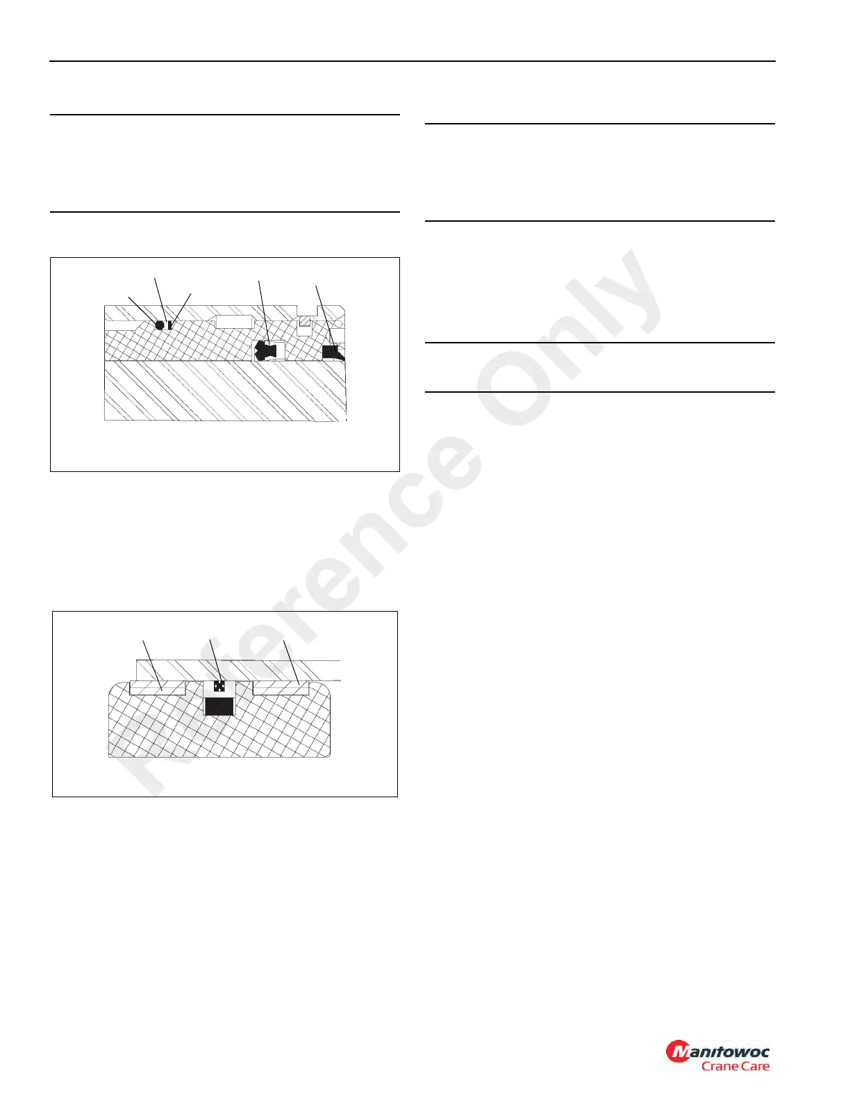
1. Install the replacement seal and wiper ring in the inside
of the head (Figure 2-53).
2. Install the replacement O-ring, backup ring and retaining
ring on the outside of the head (Figure 2-53).
3. Lubricate the rod with clean hydraulic oil.
4. Slide the head, retaining ring end first, onto the rod.
5. Install the replacement wear rings and seal on the
outside of the piston (Figure 2-54), and the O-ring on the
inside of the piston.
6. Install the piston on the rod and secure with the locknut.
7. Lubricate all parts freely with clean hydraulic oil.
8. Remove the cover from the barrel. Insert the rod and
attached parts into the barrel with a slight twisting
motion.
9. Push the head into the barrel. Use a spanner wrench
and tighten the head.
10. Pressurize and cycle the cylinder with hydraulic oil
pressure. Test the cylinder at 207 bar (3000 psi). Check
for proper operation and any leakage. Make repairs as
needed.
OUTRIGGER JACK CYLINDER
Description
The four outrigger jack cylinders (Figure 2-55) each have a
hollow rod for internal porting. Each cylinder has a 11.4 cm
(4.5 in) diameter bore. A port block is welded to the rod of
each cylinder and a pilot operated check valve is threaded
into each port block. The retracted length of the cylinder from
the end of the barrel to the center of the rod’s port block rod
bushing is 112.06 ± 0.030 cm (44.12 ± 0.12 in). The
extended length of the cylinder from the end of the barrel to
the center of the rod’s port block rod bushing is 165.4 ± 0.030
cm (65.12 ± 0.12 in). Its stroke is 53.34 cm (21.0 in). A wiper
ring prevents foreign material from entering the cylinder. O-
rings and other seals prevent internal and external leakage.
The cylinder weighs approximately 63.30 kg (139.5 lb).
Maintenance
Disassembly
NOTE: Any maintenance requiring disassembly of the
cylinders should include replacement of all seals
and rings. A seal kit will supply the required items.
CAUTION
When installing new seals and rings, avoid stretching
seals or scratching the grooved or gland surfaces. Make
sure parts are clean before and during assembly. Make
sure seals and rings are installed in the proper order.
FIGURE 2-53
O-ring
Backup Ring
Retaining RIng
Seal
Wiper Ring
6296
FIGURE 2-54
Wear Ring
Wear Ring
Seal
6295
CAUTION
Exercise extreme care when handling the rod. Damage to
the rod surface may cause unnecessary maintenance
and expense. Also, take care to avoid damaging grooved
or gland surfaces or rings or seals during rod insertion.
CAUTION
Do not use air pressure to cycle or pressurize the cylinder.
Reference Only

 Loading...


