Grove Published 01-29-2015, Control # 512-01 2-51
TMS700E SERVICE MANUAL HYDRAULIC SYSTEM
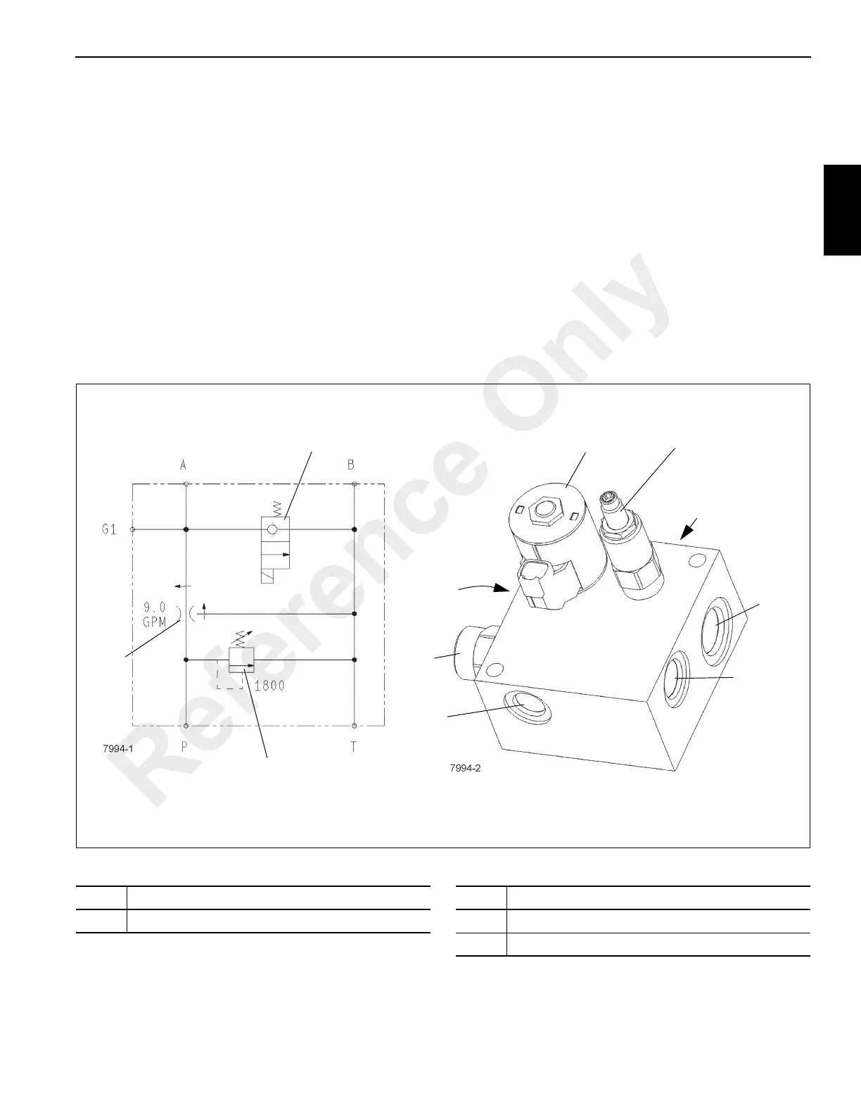
AUXILIARY WATER JACKET COOLER
FLOW CONTROL VALVE
Description
The auxiliary water jacket cooler flow control valve
(Figure 2-38) is located on the left side of the auxiliary water
jacket radiator. It provides a maximum flow of 9 gpm of oil to
the auxiliary jacket water cooler motor/bypass loop. The
excess flow is returned to the hydraulic reservoir.
Maintenance
Removal
1. Tag and disconnect the hydraulic lines from the valve.
Cap or plug all openings.
2. Disconnect the wires from the control valve.
3. Remove the two bolt/nut assemblies that hold the valve
to the support bracket.
Installation
1. Position the valve on the support bracket and secure
with the two bolt/nut assemblies.
2. Connect the hydraulic lines to the valve as marked
during removal.
3. Connect the wires to the control valve.
4. Check valve and hydraulic connections for leaks. Make
repairs as necessary.
Item Description
1 Flow Control Cartridge
Item Description
2 Relief Valve (124.11 bar [1800 PSI])
3 Flow Divider
Reference Only

 Loading...


